IPSec Peer Backup Behavior in Asymmetric Routing Scenario
IPSec Peer Backup feature is a name that is not really widely know to all the cisco guys out there because it is mostly hidden behind the ability to put two (or more) IPSec peer IPs to a single crypto-map statement. In this article, I will provide a little insight to this feature that, with luck, will make you appreciate the complex operations with all the management/transport IPSec tunnels that must be handled when this feature is in use. Recently I put this feature to the limits in asymmetric routing environment and I want to share some lab results.
Contents
Peer Backup Feature
Let’s start with the basic topology and configuration of the feature itself. I will not provide IPSec configuration details as I am sure there are many sources for this on the internet, I will only show the interesting parts.

In this lab, I used Cisco ASA to use the IPSec Peer Backup feature, but the exactly same functionality is available on IOS routers as well. So in my lab, the configuration was:
crypto map IPSec_map 10 match address ecnrypt_acl
# NOTE TWO PEERS IN THE FOLLOWING LINE
crypto map IPSec_map 10 set peer 5.100.34.3 5.100.42.2
crypto map IPSec_map 10 set transform-set myset
crypto map IPSec_map interface outside
If you want, you can change this lab topology from ASA to IOS router and just change the crypto-map to IOS based syntax:
crypto map mmax-map 10 ipsec-isakmp
  set peer 5.100.34.3
  set peer 5.100.42.2
  set transform-set myset
  match address encrypt_acl
Routing asymmetry configuration
The routing is setup in the following way using only static routes to create the whole scenario with asymmetric routing and R4 “playing” Internet:
1. R4 simulates Internet. R4 routes only between the directly connected networks.
2. ASA, R2 and R3 have default route pointing to the Internet (R4)
3. R5 has default route pointing to ASA
4. R6 has routing to 10.26.242.1/24 via R2 and 10.26.242.1/24 via R3
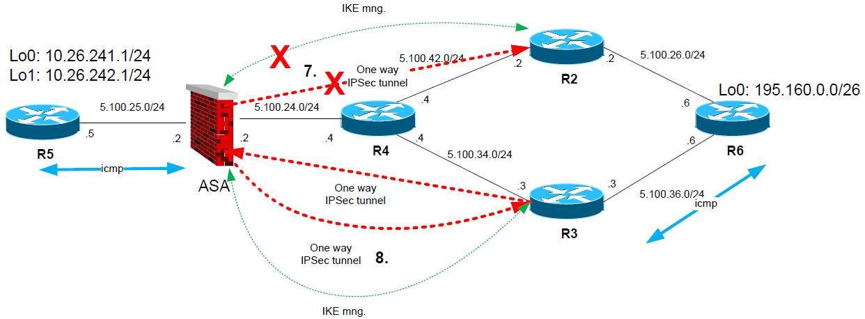
Scenario A
(ASA starts communication with “wrong” peer for returning traffic)
1. R5 sends “icmp” ping from 10.26.241.1 to 195.160.0.1 (on R6).
2. ASA matches crypto traffic and chooses first peer 5.100.34.3 (R3) and establishes IPSec tunnel for encryption domain 10.26.241.0/24-195.160.0.1/26
3. Icmp ping is transported encrypted to R2, R2 decrypts the packet and forwards to R6.

4. R6 gets Icmp ping “echo request” and generates icmp “echo reply” packet.
5. R6 however has next hop of 5.100.26.2 (R2) as next hop for destination of the reply packet (10.26.241.1). So the packet is forwarded to R2.
6. On R2, the packet will match the crypto map and R2 starts to negotiate IPSec tunnel to ASA.

7. Once the R2 successfully establishes the tunnel to ASA, ASA will graciously drop the tunnel to R3
8. ALL subsequent communication is flowing between 10.26.241.0/24-195.160.0.0/26 via IPSec tunnel of ASA to R2
Scenario B
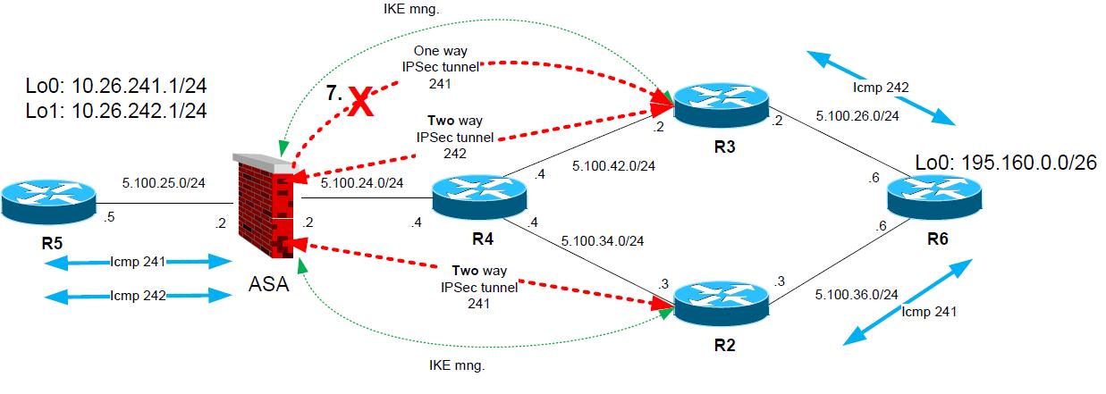
(Encryption domain on ASA side has two subnets (on lo0/lo1) and R6 has different “return” routes to these destinations via R2 and R3):
1. R5 sends “icmp” ping from 10.26.241.1 to 195.160.0.1 (on R6). And also from 10.26.242.1 to 195.160.0.1 (on R6).
2. ASA matches crypto traffic and chooses first peer 5.100.34.3 (R3) and establishes IPSec tunnel for both encryption domains 10.26.241.0/24-195.160.0.1/26 and 10.26.242.0/24-195.160.0.1/26
3. Icmp pings are transported encrypted to R2, R2 decrypts the packets and forwards them to R6.

4. R6 gets Icmp ping “echo requests” and generates icmp “echo reply” packets for both destinations.
5. R6 however has next hop of 5.100.26.2 (R2) as next hop for destination of the reply packet (10.26.241.1). So the packet is forwarded to R2. For 10.26.242.1 the next hop is R3.
6. On R2, the packet will match the crypto map and R2 starts to negotiate IPSec tunnel to ASA.

7. Once the R2 successfully establishes the tunnel to ASA, ASA will graciously drop ONLY phase 2 Ipsec transport tunnel for encryption domain 10.26.241.0/24-195.160.0.1/26 previously established with R3
8. ALL subsequent communication between 10.26.241.0/24-195.160.0.0/26 is flowing via IPSec tunnel from ASA to R2, and for 10.26.242.0/24-195.160.0.0/26 vie tunnel from ASA to R3
Summary
In summary, this small ability can be a life-saver when used and it is very easy to use as you only add multiple peer IPs to the crypto-map definition, yet the mechanisms behind the scenes are complex.
I hope you enjoyed this article first new year (2012) article.
Peter

