Basic Load-Balancer Scenarios Explained
Load-Balancing is in principle a wonderful thing really. Once you know the basic principles, every load-balancer from any vendor is very easy to configure once you you know the three basic scenarios that are mostly deployed in real life. If you don’t, do not worry and just read on. This article is an introduction to the load-balancers three basic configuration scenarios to give you an overview before other articles start to explore load-balancing solutions in more detail.
The basic load-balancer scenarios are:
- Two-Arm (or sometimes called In-Line)
- One-Arm
- Direct Server Response
Without more delays, lets start…
Two-Arm Load-Balancer (Routed mode)
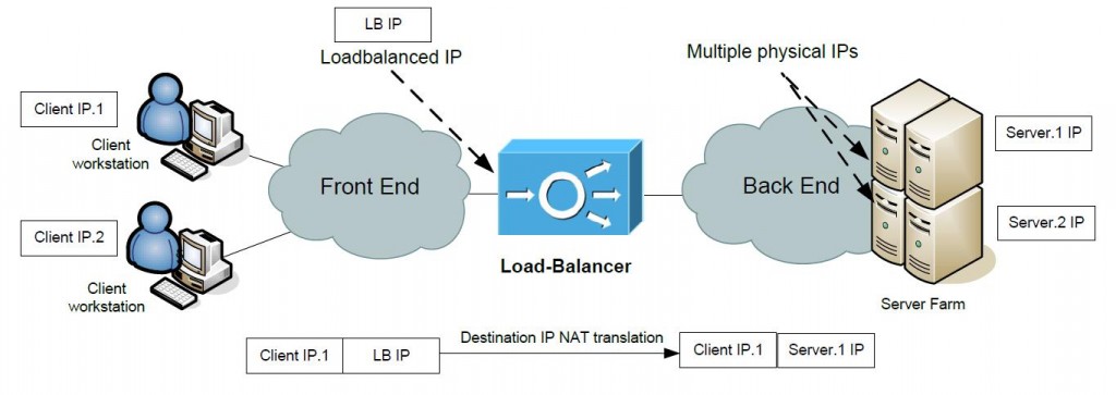
Two-Arm is basic scenario where you have a server farm in one side of the network (Back End) and the load-balaner is essentially the default gateway router for the physical servers in the Back End network.
In general Two-Arm can also be used in something called “bridge mode” or “transparent mode”. The scenario diagram would be the same with the exception that the Load-Balancer would be essentially a switch load-balancing by modifying L2 frames. But I will only focus on the routed mode as it is the most common and more easy to understand. For the “transparend mode”, the same traffic paths would apply, but the load-balancer has to intercept traffic at L2 to load-balance by changing L2 frames to get them to the physical routers in server farm.
But let’s get back to the routed mode scenario as it is much simpler, cleaner, more easy to troubleshoot and therefore deployed much more often. To be honest I didn’t yet seen an two-arm scenario deployed as switched mode in real production networks because there is no need for this most of the time and there are no big advantages against the Two-Arm in routed mode.
Basic scenario of routed two-arm solution can be seen on next picture that. The picture is generalized for overview purposes and you can note the Load-Balancer separating users and server physically, therefore all the traffic has to go via the Load-Balancer.
As you can agree, the Load-Balancer is also a router between the “Front End” and “Back End” networks. As such, he can simply do destination IP NAT in client request coming to the load-balanced virtual IP and forward the packet to one of the servers in server farm. During this proces, the destination physical server is chosen by the load-balancing algorithm.
Return traffic is going back via the Load-Balancer and the source IP is again changed to the virtual load-balanced IP in the response to the Client.
One-Arm Load-Balancer
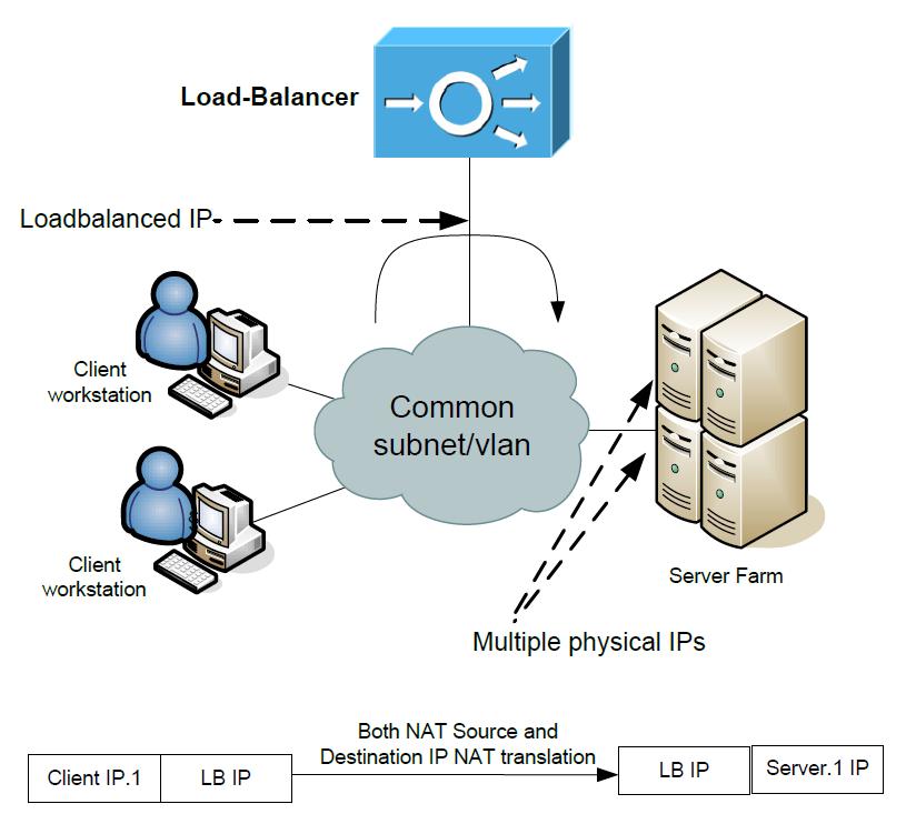
One-Arm means that the Load-Balancer is not physically “in-line” of the traffic, but as you might understand right now, it has to get into the way of traffic somehow, to have control over all the Client to Server connections going in both ways. So let’s have a look at the following topology with One-Arm solution to understand what the Load-Balancer has to do.
It is not important how far away the Client worksations are, they can be behind internet or in the same LAN and the load-balancing would be the same. However, the Load-Balancer is using only one interface and this interface is on the same L2 network with all the servers.
The traffic that the client initializes will get to the Load-Balancer that has the virtual load-balanced IP. The load-sharing algorithm will pick a physical server to which the Load-Balancer will forward the traffic with destination IP NATed to the physical IP of the server and forward it out the same interface towards the physical server.
BUT the Load-balancer also needs to do source IP nat so that the server reply will go back from the server to the Load-Balancer and not directly back to the Client, who is not expecting a reply directly from physical server IP. From the physical servers perspective, all the traffic is coming from Load-Balancer..
Once you understand the above paragraph, you understand the One-Arm solution fully.
PS: The source IP NAT can be both to the load-balanced IP (which is the most common for implementation not expecting more than 3000 hosts*) or to any other nat pool that the servers will forward to the load-balancer back.
*The theoretical limit of NAT (or PAT) hiding entire networks behind a single IP is 65355 sessions, but in real life the pragmatical limit is somewhere around 3000 connections (this value is recommended by Cisco)
Direct Server Response (or sometimes called Direct Server Return)
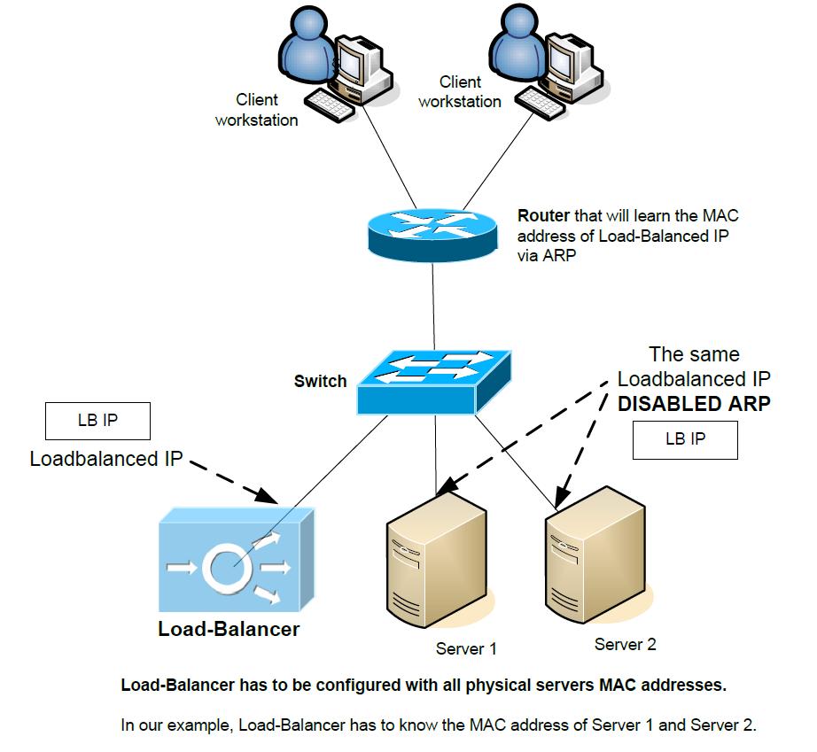
Last basic Load-Balancer scenario is Direct Server Response, to understand this scenario, we need to bring a switch into the topology. As we hopefully all know, switches learn about MAC addresses as they see frames coming on ports with source MACs. Also imagine that we have a router that has to know the MAC address of the Load-Balanced IP on the last L3 hop. With the picture below, you can already spot the “trick” this scenario tries to present here once you notice the disabled ARP on physical servers.
In this scenario, Load-balancer only sees the incoming part of client-server traffic and all the returning traffic from physical servers is coming directly back to the client IP. The biggest advantages of this solution is that there is no NAT and the Load-Balancer throughput is only used in one way, so less performance impact for the Load-Balancer system. Disabling ARP on a physical server is not a difficult task.
Disadvantages however are that you have to manually configure the Load-Balancer with all the server MAC addresses and might be more difficult to troubleshoot with only one way traffic seen by the Load-Balancer on the whole L2 segment.
Sumamry
I hope you enjoyed this super quick overview that tried to present the basic Load-Balancer scenarios that you can encounter out there.
Which Load-Balancer scenario do you prefer or what Load-Balancer configuration did you already deployed ? Let us all know in the comments.
Peter












2 comments ...
Comments are closed.