


HPE’s DCN / Nuage SDN – Part 2 – First Steps Creating Virtual/Overlay Customer Network
In the previous part 1, we have installed basic HPE DCN system on a group of ESXi hosts. But we didn’t actually done anything inside it, so lets fix this by creating a first “HelloWorld” customer that we will call “NetworkGeekStuff” and deploy some virtual machines to this virtual network. In this part we are going to fix that and we will create a very basic virtual customer, a username/password for that customers administrator and create a small 3 tier ( database / internal / dmz) network using HPE DCN’s overlay virtual network. And at the very end, we are going to connect to this network a few virtual machines.
Index of article series:
- HPE’s DCN / Nuage SDN – Part 1 – Introduction and LAB Installation Tutorial
- HPE’s DCN / Nuage SDN – Part 2 – First Steps Creating Virtual/Overlay Customer Network
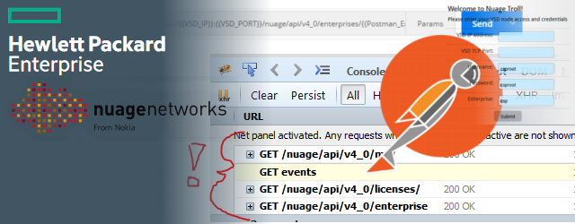
- HPE’s DCN / Nuage SDN – Part 3 – REST API introduction
Contents of Article
- Starting LAB state
- Step 1. Creating VSD company
- Step 2. Creating users / group permissions
- Step 3. Creating a virtual network
- Step 4. Starting a virtual network instance
- Step 5. Adding user permissions to your instance
- Step 6. Adding a VM to the network
- Step 7. Repeat previous step for more VMs
- Step 8. Ingress/Egress Security Policies
- Step 9. (Optional) Homework VRS/VSC Verifications
- Summary
Starting LAB state
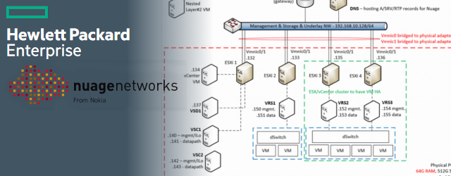
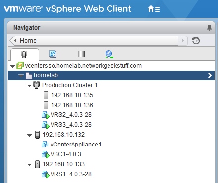
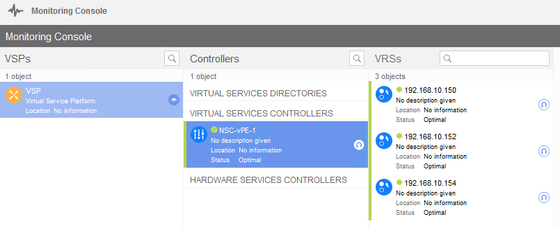
We will start exactly where we ended on previous part 1, but to double-check, I am going to show the main views of my vCenter and VSD environment to show how “empty” it is after a pure install that we did so far. So starting with this, below is my view on vCenter boxes, with one management ESXi host (192.168.10.132), one single ESXi host (192.168.10.133) with VRS installed and an ESXi cluster (192.168.10.135/192.168.10.136) with a dual VRS installation from last lab.
Step 1. Creating VSD company
So first step is simple (at least for now as we will not go in this tutorial into company templates and use dafult template), when you first login to VSD as csproot, you see an empty screen because there are no companies and there is a big plus “+” sign in the white space, when you click this you can create a new company. In HPE DCN’s terminology a company is called “Enterprise” so from this point I will use this name. So lets look at the picture below, where I have simply created a “NetworkGeekStuff” enterprise, with default profile and I selected a private AS number 65512 (as private AS numbers are 65512-65535), but you can also leave this blank, this will be used later in future tutorials for BGP peering with WAN.
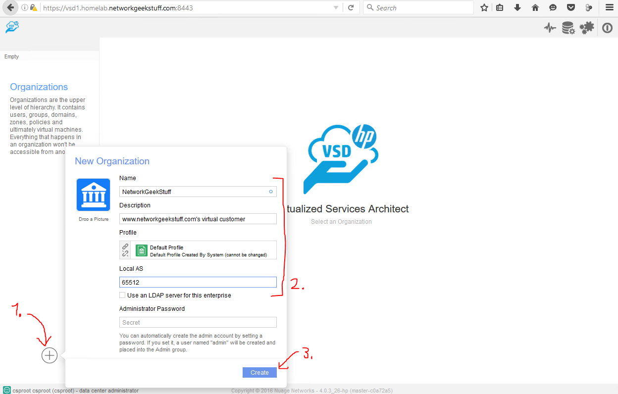
Next time when you enter VSDs default view, you can select this enterprise from the list on the left side.
Step 2. Creating users / group permissions
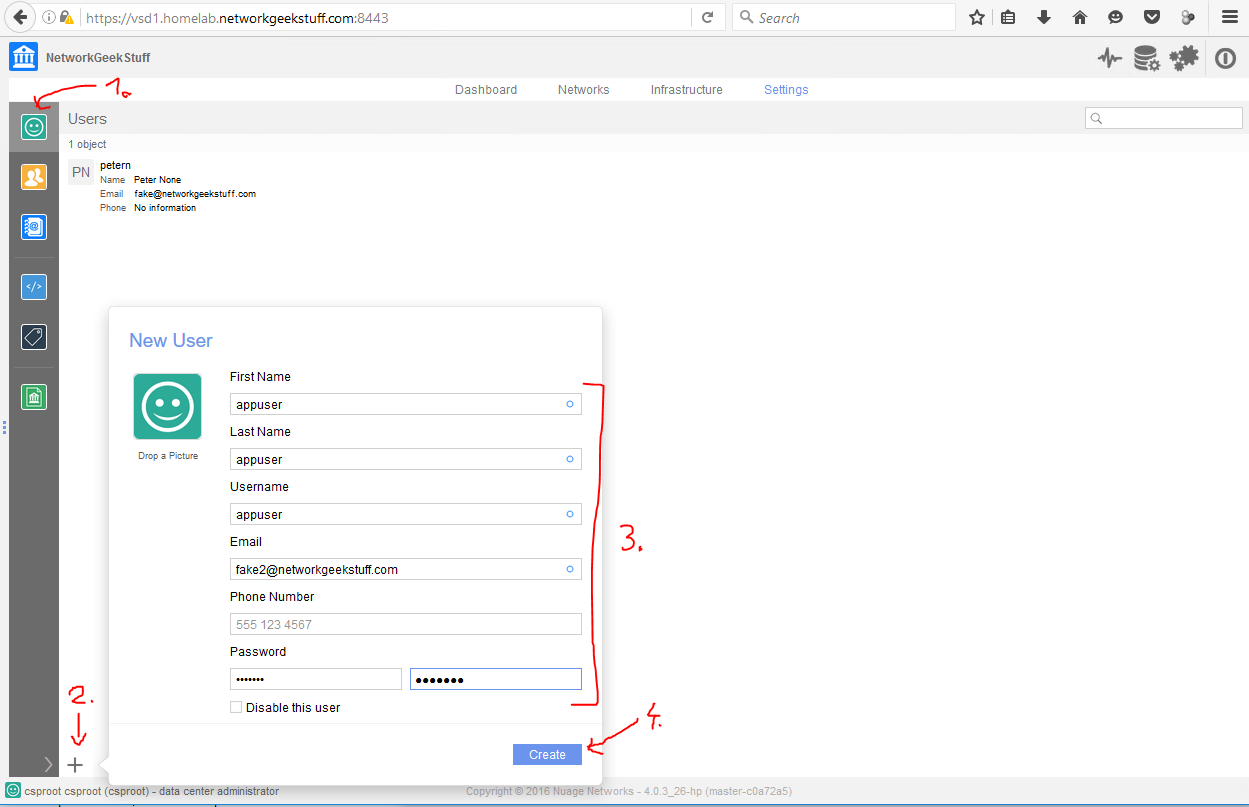
In our installation and to create a new Enterpise we used the default super-admin called “csproot”, but for Enterprises it is very usefull to create at least two users, one will be an admin for a specific Enterprise, and the second one would be a passive read-only users, but he will be an owner of all the virtual machines later. In our example here, we will create two users:
- petern – this will be my admin user for the enterprise network design
- appuser – this will be a read only

Next step is to put these two users into their groups to give them permissions, by default there three groups in VSD:
- Administrators – essentially like csproot, but only for scope of this enterprise
- Network Designers – limited to editing network templates and topology of the overlay in VSD
- Everybody – default group where every user ends after creation with nearly no control rights
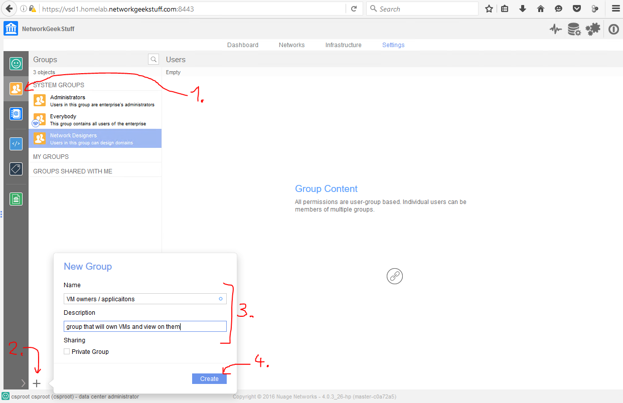
What we are going to do next is that we are going to add my admin/network designer user “petern” to the Network Designers group (this is because you do not need Administrators for the tasks we will be doing in this tutorial) and we will create a new group called “VM owners / applications” and add the “appuser” user to this group. This is to separate our special user to additional group and then we can simply give this group only limited permissions to “own” VMs connected to the topology, but not edit the topology. This is all following HPE DCN’s recommendation that network designers and compute/VM owners should be two separate groups.
In first part, lets create the new group called “VM owners / applications”:
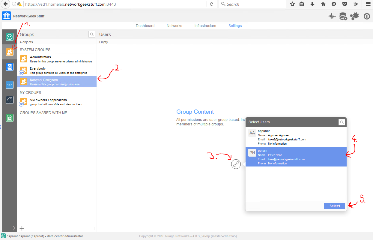
Now that we have the additional group, lets add petern user to group “Network Designers”:
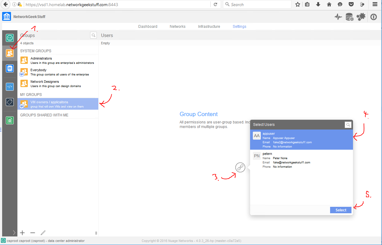
Next add “appsser” to “VM owners / applicaitons” group:
Step 3. Creating a virtual network
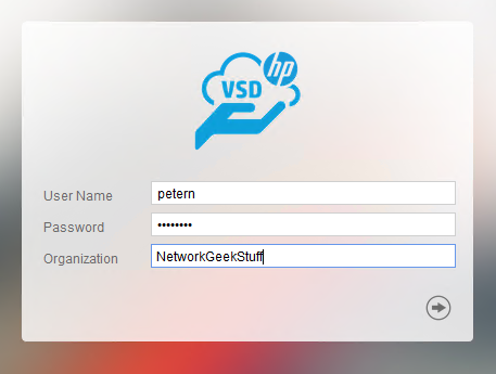
Now finally the great virtual network design work! HPE DCN has a concept of creating a network design as a template and then creating an instance of that template. So lets begin with what with re-logins from the VSD from csproot to our “network designer” user we created in previous step that for me is called “petern”.
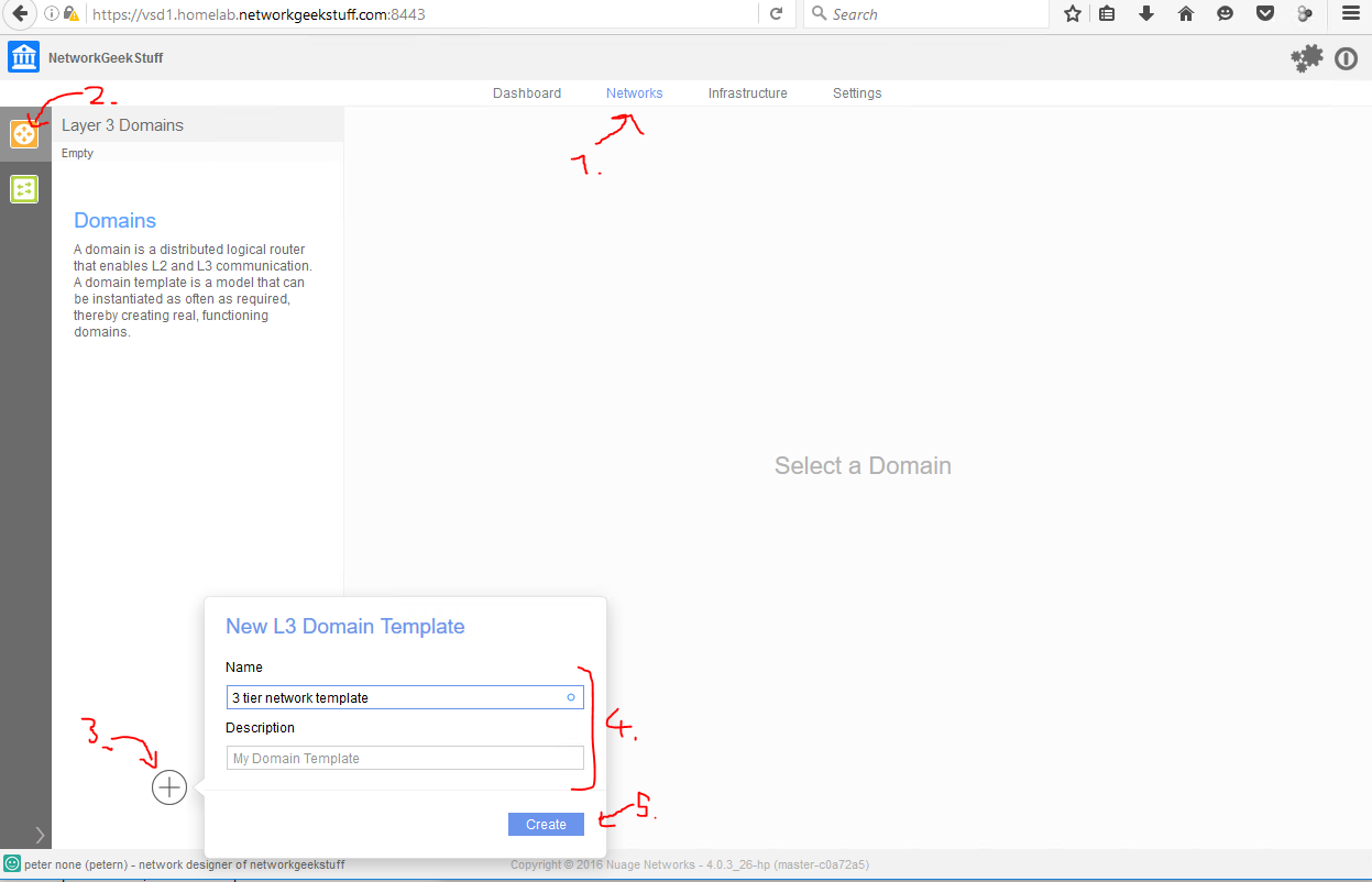
Once logged in, we can create an L3 domain template, this is template on creating a layer 3 (OSI layers model should be known to you as network guy!) template, first as empty template simply:
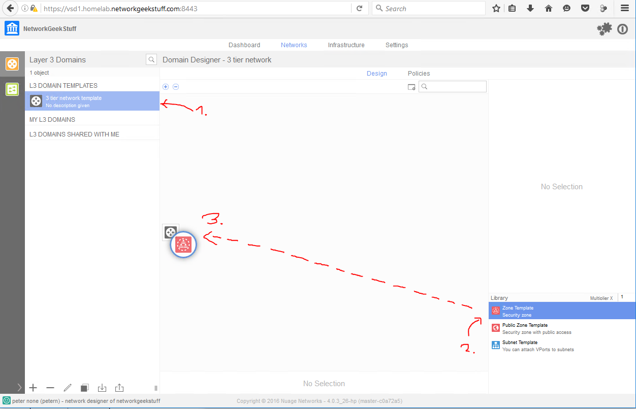
Next, select that template, and we will start building a typical 3-tier network that will consist of:
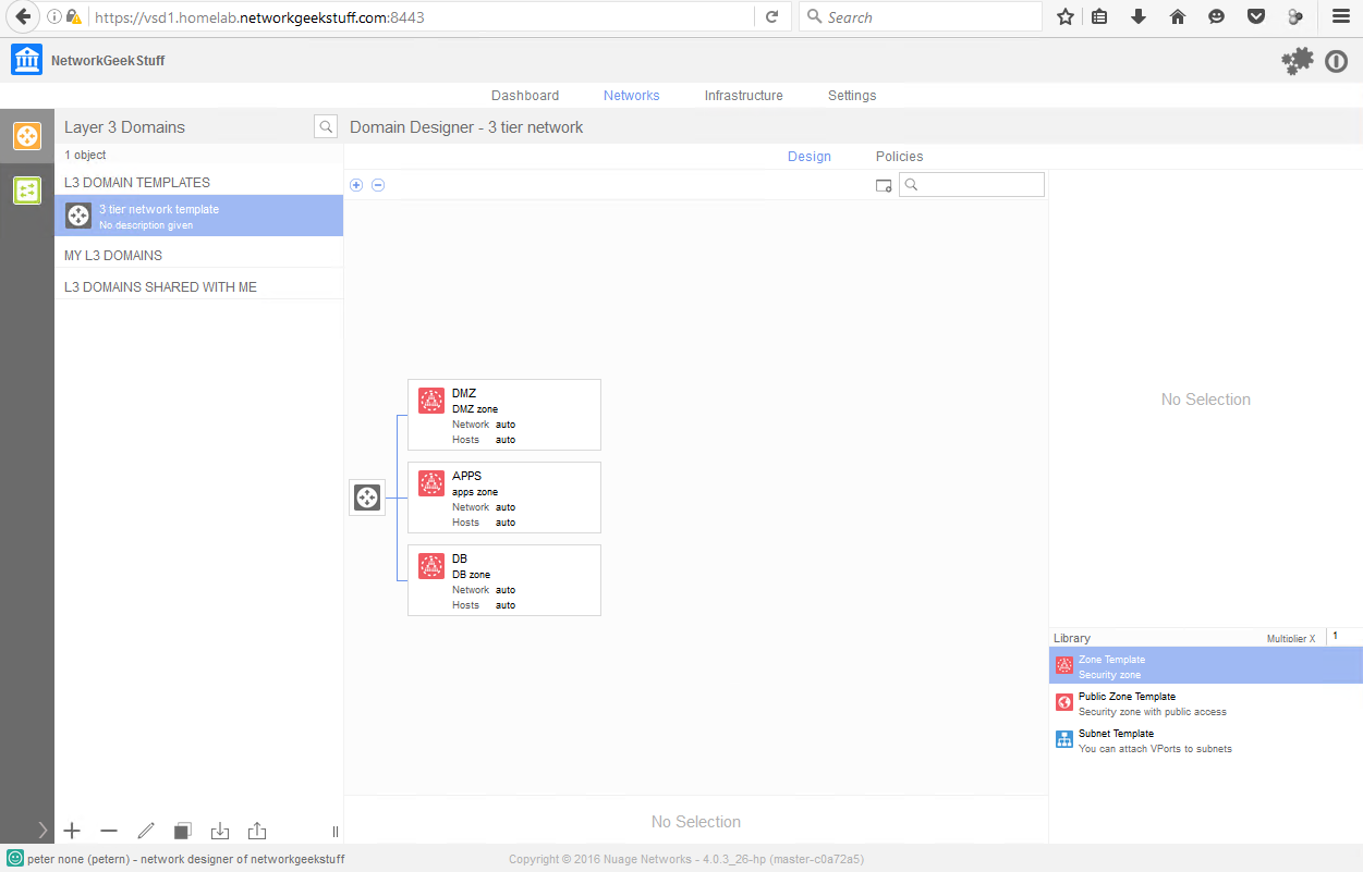
- DMZ zone – this is a security zone for separating front-end systems (like systems with access to Internet, but right now we do not have any internet here)
- APPS zone – this is where application servers should be hosted, it is an internal zone for the enterprise
- DB zone – this is where database servers should be hosted to be isolated from application servers they are serving
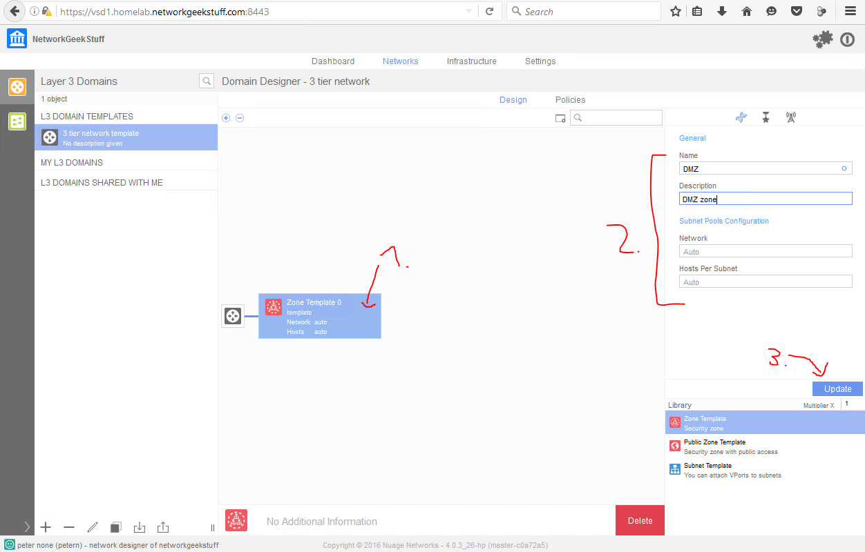
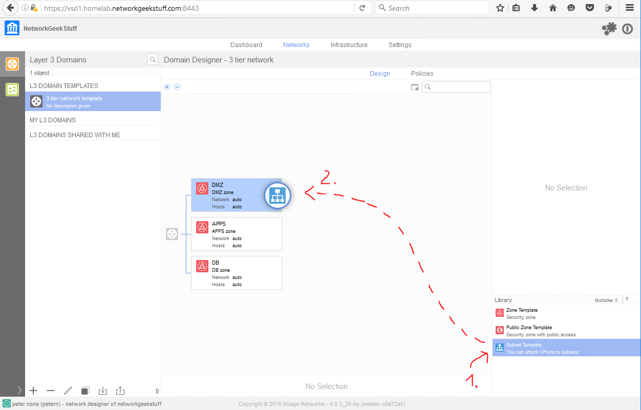
To create such template in VSD, select the template, and simply drag&drop three zone templates to the central black “router icon” like this, then you can edit the name of a zone. If you do this three times like on the pictures below, you will end with a nice 3 tier template with three zones.

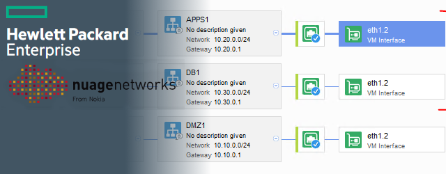
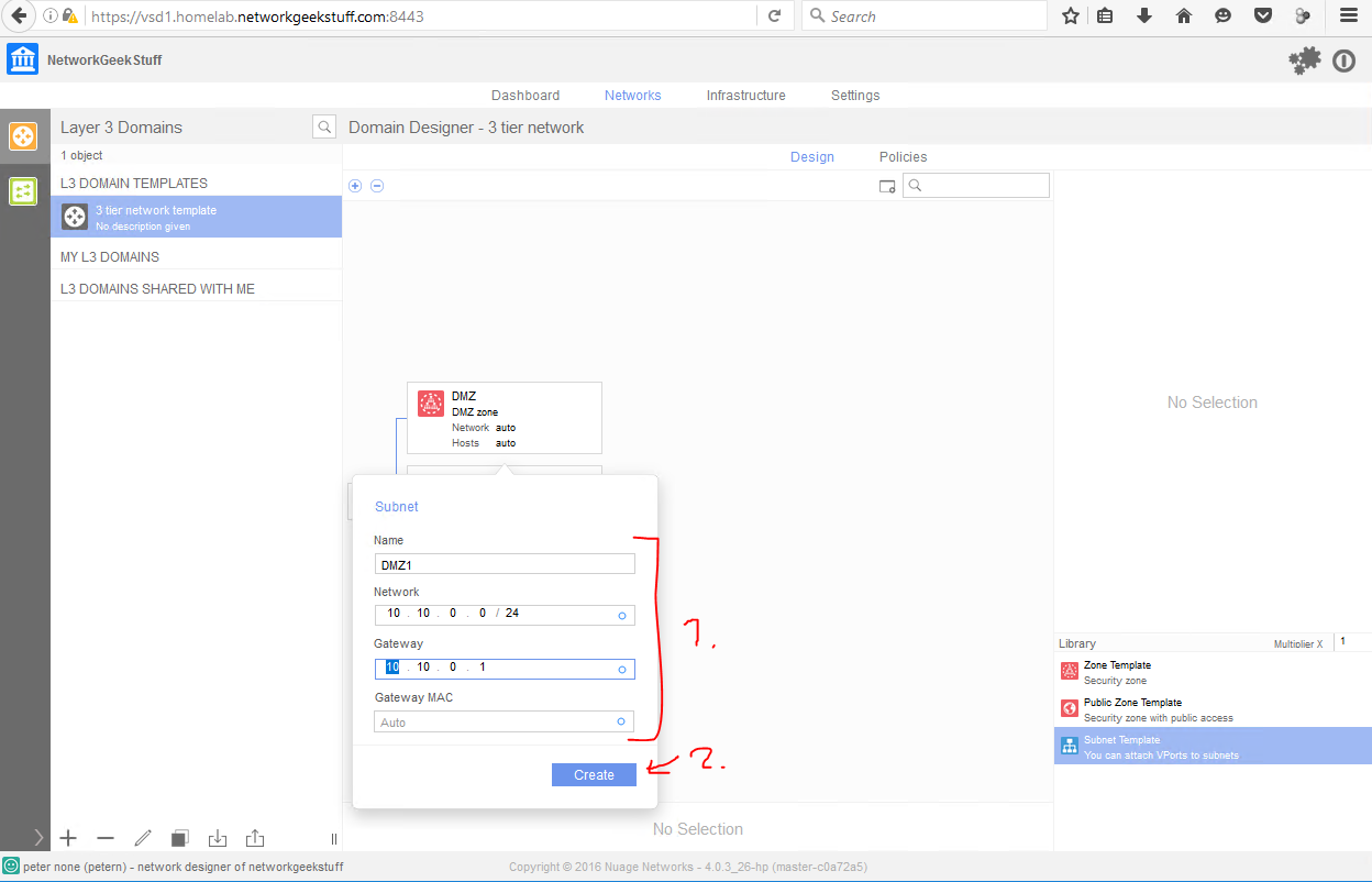
OK, we have zones now. For the network however, we still need IP subnets, for this we need to drag to each zone at least one subnet, so drag&drop one subnet template to each zone, name them DMZ1 / APPS1 / DB1 and if you want, you can choose what IP ranges to use in each. I am going to start with a simple scheme of:
- DMZ1 – 10.10.0.0/24
- APPS1 – 10.20.0.0/24
- DB1 – 10.30.0.0/24

Step 4. Starting a virtual network instance
This is now actually a super quick step, simply select the template you want to start and hit the “Instantiate” button/icon below and give the instance a name.
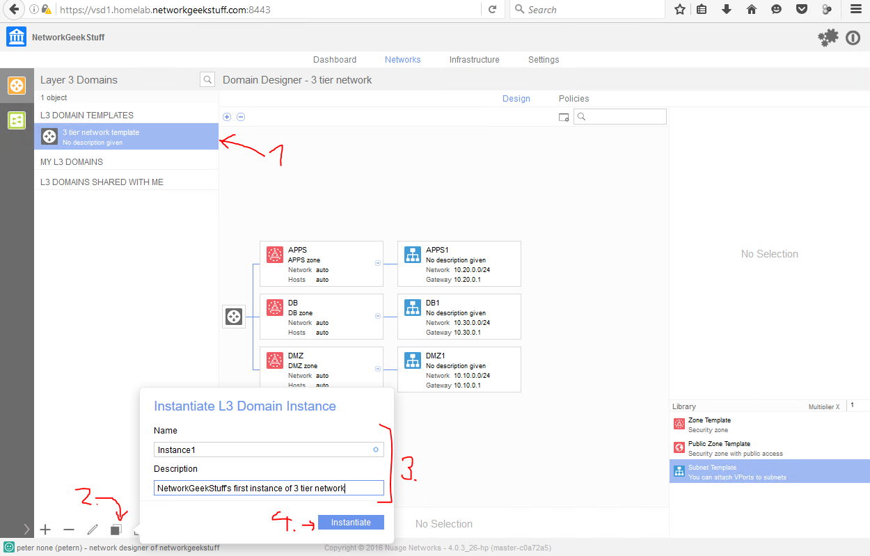
Congratulations, you now have an instance running under the domains list with your instance name.
Step 5. Adding user permissions to your instance
Right now we have an instance running, but nobody other than admin has access and permission to actually deploy (like placing a VM) to this instance, we should at minimum setup these permissions. We can quickly assign these permissions with a few clicks.
- Network Designers should have “DEPLOY PERMISSIONS” to the instance (things like doing live changes to instance)

- VM owners / applicaitons should have “READ PERMISSIONS” to the instance (to know the topology)
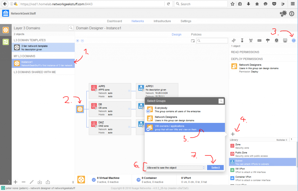
- VM owners / pplicaitons should have “USE PERMISSIONS” to each zone in order to be allowed to deploy a VM to it

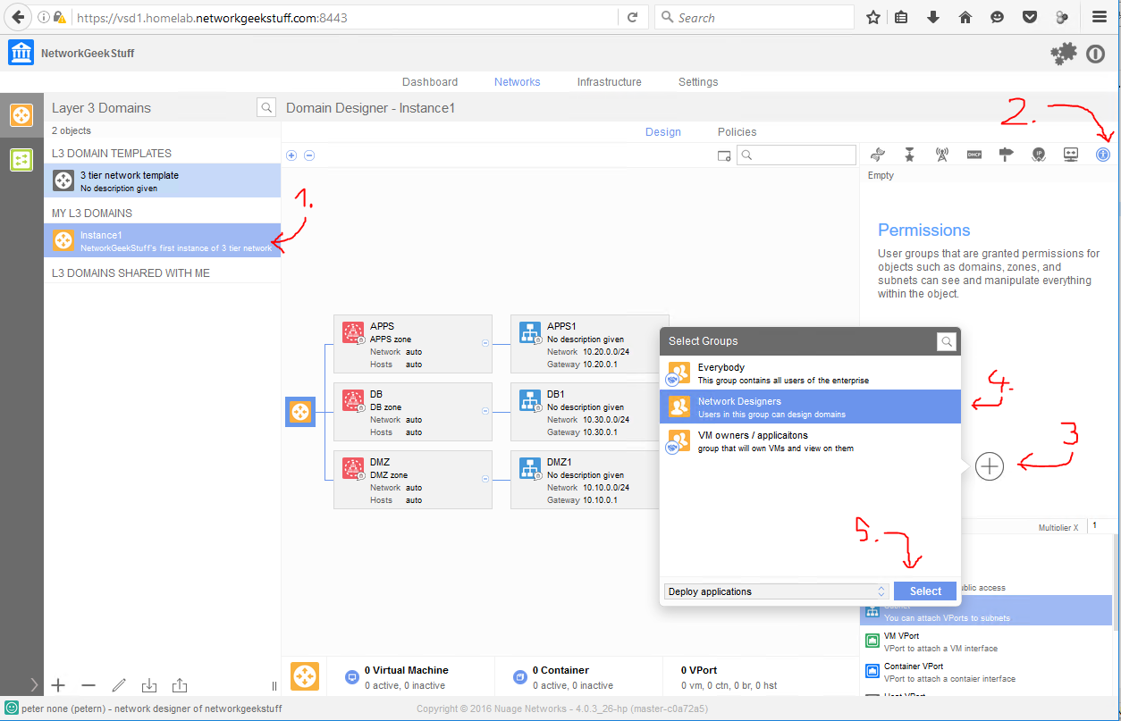

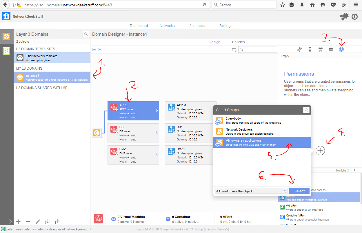
After these steps, you have an instance and also basic permissions management established.
Step 6. Adding a VM to the network
Now things become interesting. HPE DCN is actually not adding VMs to the network by any particular action inside VSD. Adding a VM will be a simple vCenter tasks, the only thing we have to do in addition, is to edit the VM’s metadata and manually enter a few special parameters to indicate to which Enterprise / Instance / Zone / Subnet the specific VM should be placed.
What you need: OVF/OVA image of a small linux to play the role of customer VM server
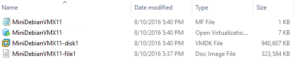
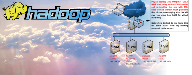
I have created for myself a very small VM in a form of OVF/OVA image that only needs 128MB of RAM that I will be deploying via vCenter. If you do not have your own OVF/OVA image, I strongly suggest that you create one for yourself or download some from the internet. Alternativelly, you can install a normal VM in vCenter using traditional installation from installation media and then exporting that installed VM to an OVF/OVA directly from vCenter.
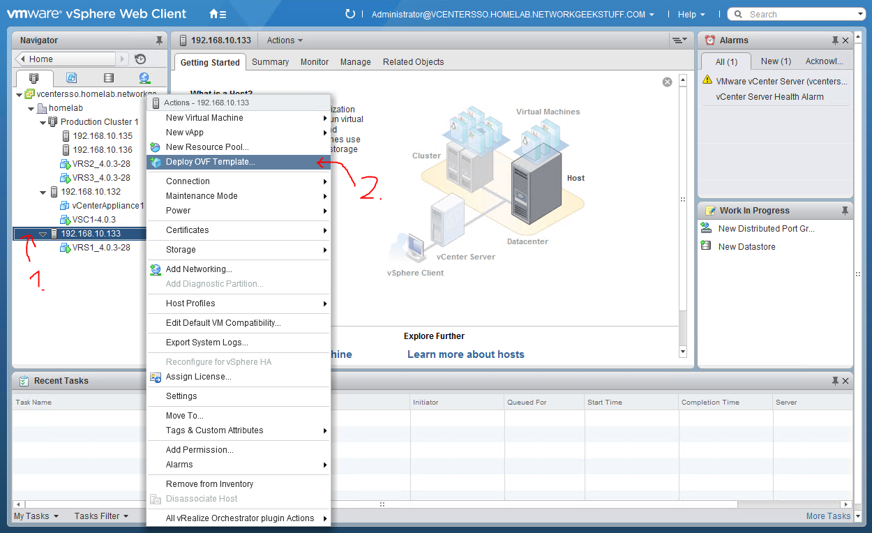
Step 6.1 Deploy OVF image in vCenter
The first step here is to simply use vCenters “Deploy OVF Template .. ” wizard to put a VM to one of the clusters. for first image, I am going to use the stand alone production cluster 192.168.10.133 that already has a VRS installed.
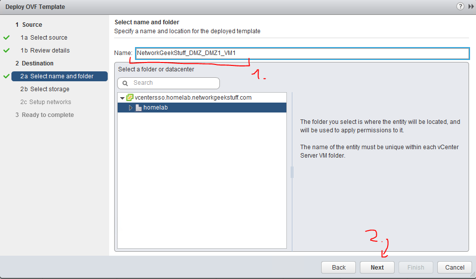
In regards to the deployment process, I only recomment that you name your VM based on the instance / zone / subnet you want to add it into, for example right now I want to add the VM to the following zones:
- Enterprise: NetworkGeekStuff
- Instance: Instance1
- Zone: DMZ
- Subnet: DMZ1
So I have named the VM as “Networkgeekstuff_DMZ_DMZ1_VM1“. I missed the intances to make the name a bit shorter and added “VM1” at the end indicating this is my first VM in this zone/subnet.
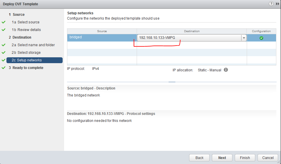
The only other mandatory task to show here is the fact that you have to add the VM to the “<ESXi host>-VMPG” port group when selecting the network interface configuration.
Step 6.2 Configuring VM’s metadata for HPE DCN’s overlay
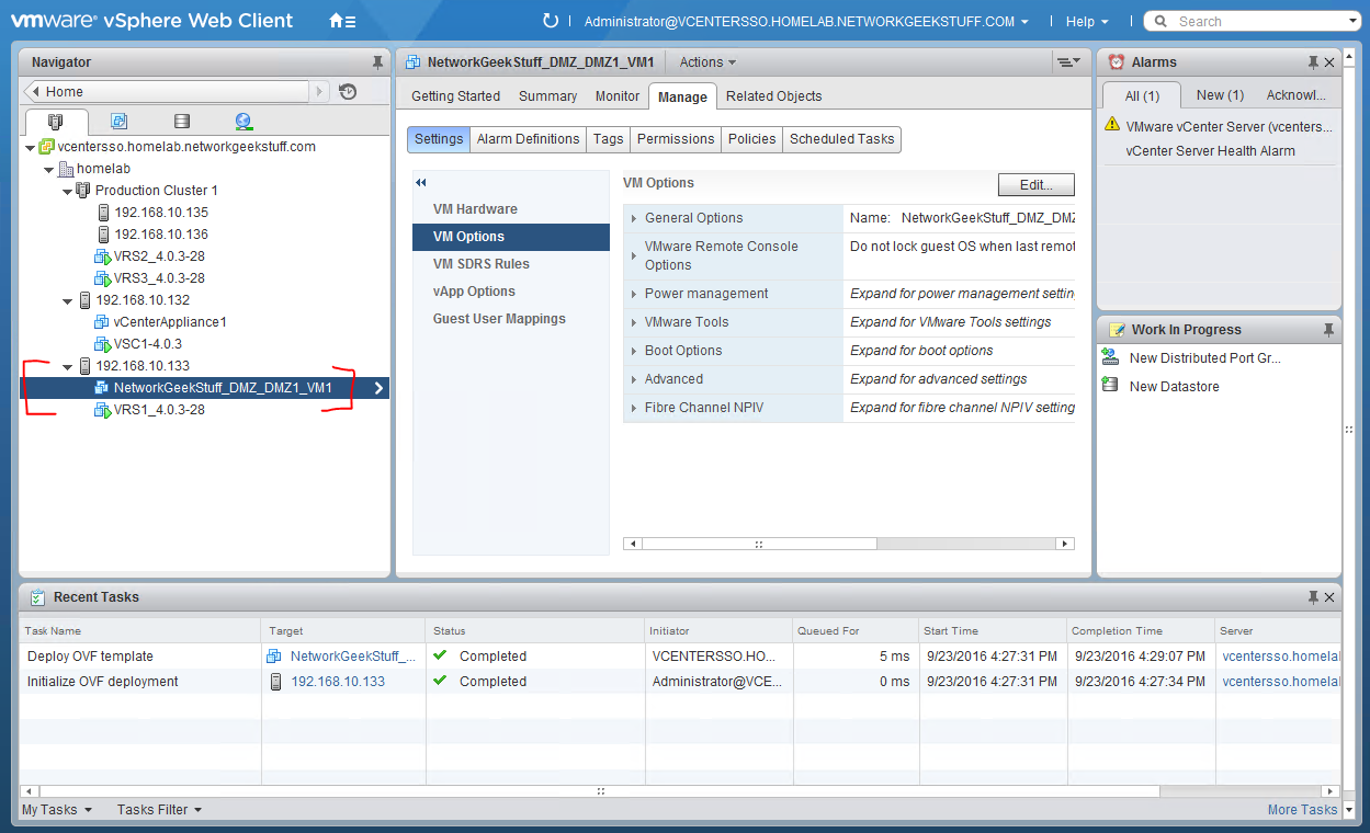
Now we should have in the vCenter a new VM deployed like seen here:
What we need to do is to create for this VM items in the metadata (or VM options) that would drive this VMs assignment to the correct network landing. These options are:
- nuage.user – controls which VSD user this VM is associated with (the user has to have “USE PERMISSIONS” for the zone
- nuage.enterprise – controls which VSD enterprise this VM is assigned to
- nuage.nic0.domain – controls which VSD Instance this VM should be connected to
- nuage.nic0.zone – controls which VSD zone this VM should be connected to
- nuage.nic0.network – controls which VSD subnet this VM should be connected to
- nuage.nic0.networktype – controls what type this interface is, right now this will be 99% of time simply “ipv4”
So lets find these options in the vCenter configuration, they are located under “Advanced” tab in the VM’s Manage-> Settings -> VM Options.
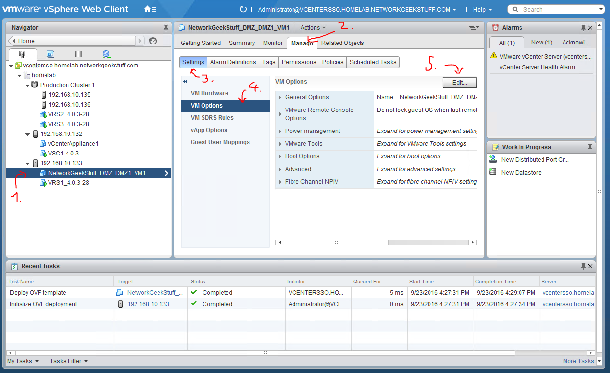
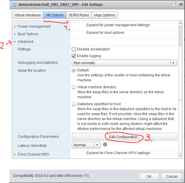
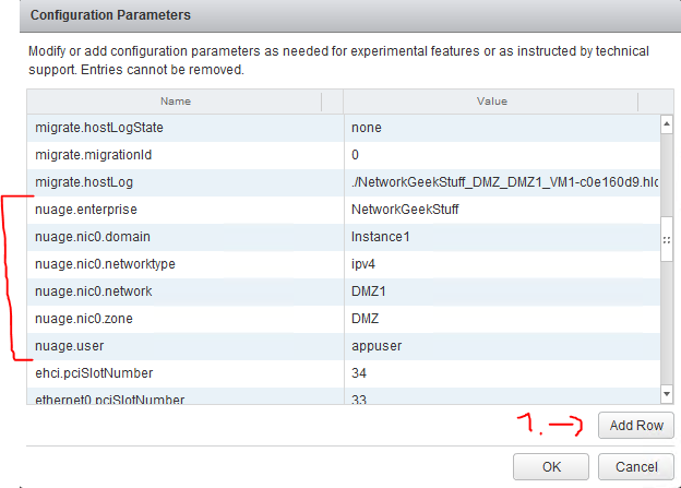
Now what we should add here is use the “Add Row..” button and add the following parameters (or modify to match your network instance):
- nuage.user – appuser
- nuage.enterprise – NetworkGeekStuff
- nuage.nic0.domain – Instance1
- nuage.nic0.zone – DMZ
- nuage.nic0.network – DMZ1
- nuage.nic0.networktype – ipv4
Here is the result:
Step 6.3 Boot the VM and check if connected
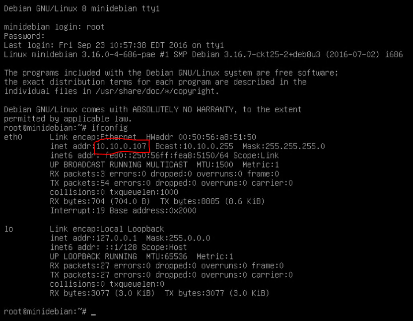
So on this point we have VM that is ready to be booted and with all the nuage parameters correctly entered, the VRS should auto-detect the new VM, and report to VSC/VSD this new VM, whilc VSD/VSCs are going to coordinate this VMs successfull connection to the overlay fabric. So lets try this simply by booting the VM.
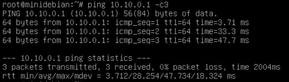
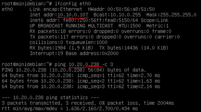
First indication that we have been successful is simply that the VM received an IP correctly, which we did as shown below. We received 10.10.0.107 what is a correct DMZ1 subnet IP. Second test is that you can ping the default gateway which is practically the VRS and created dynamically.
The second indication is that the VM is dynamically auto-detected in the VSD and you can see it in the network topology inside the subnet (click the subnet)
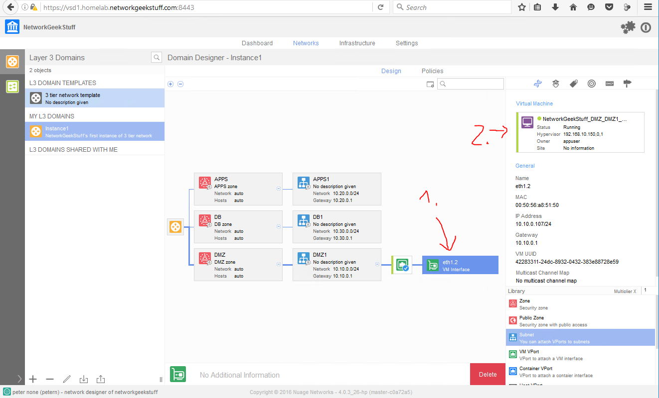
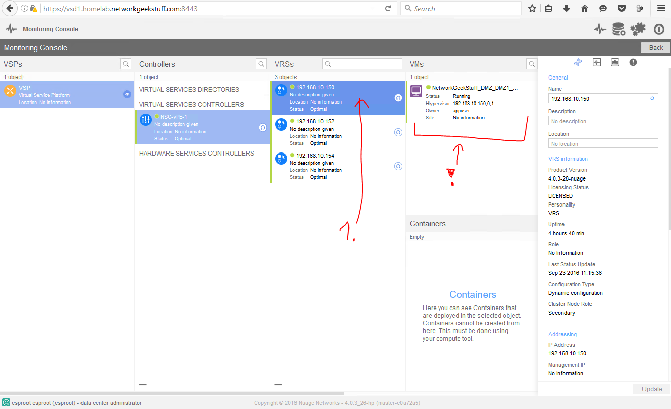
Additionally, the VM is visible under list of VMs that is handled by the VRS inside the 192.168.10.133 host that is
Step 7. Repeat previous step for more VMs
This is step is a placeholder for you to add more virtual machines to the topology, for my needs, I have added the same OVF template to other zones of APPS and DB to populate the topology, if you want you can us ANY ESXi host that has VRS installed and of course you can also add multiple more VMs to each zone/subnet as you want. My final view is this from VSD1 perspective as I have added two more VMs, one to APPS – APPS1 and one to DB – DB1 network.

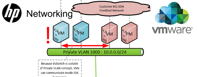
Now the final test is of course trying to ping from one VM to another one, so lets try this, my first DMZ VM got IP 10.10.0.107, one of the other VMs in APPS zone has an IP 10.20.0.238, so lets try pinging them from each other.
What is this?!! It doesn’t work!!!
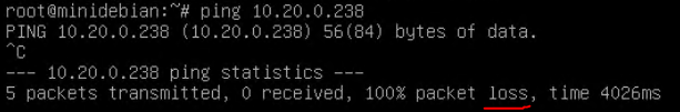
Now before you go screaming that HPE DCN is not working like I, the reason is actually by design that by default there is a policy that any input packets from VMs to the HPE DCN fabric are blocked, so we have to create a policy to unblock this first.
Step 8. Ingress/Egress Security Policies
As mentioned in Step 7, by default HPE DCN blocks any ingress packets from VMs to the fabric until allowed. This blocks zone-to-zone communication. So in this step, I am going to show you how to create some default filters that will permit our traffic.
Step 8.1. Create default “PERMIT ANY” ingress policy
If you simply want to allow everything for testing in your 3 tier network, you can simply go to “Ingress Security Policies”, hit plus sign and
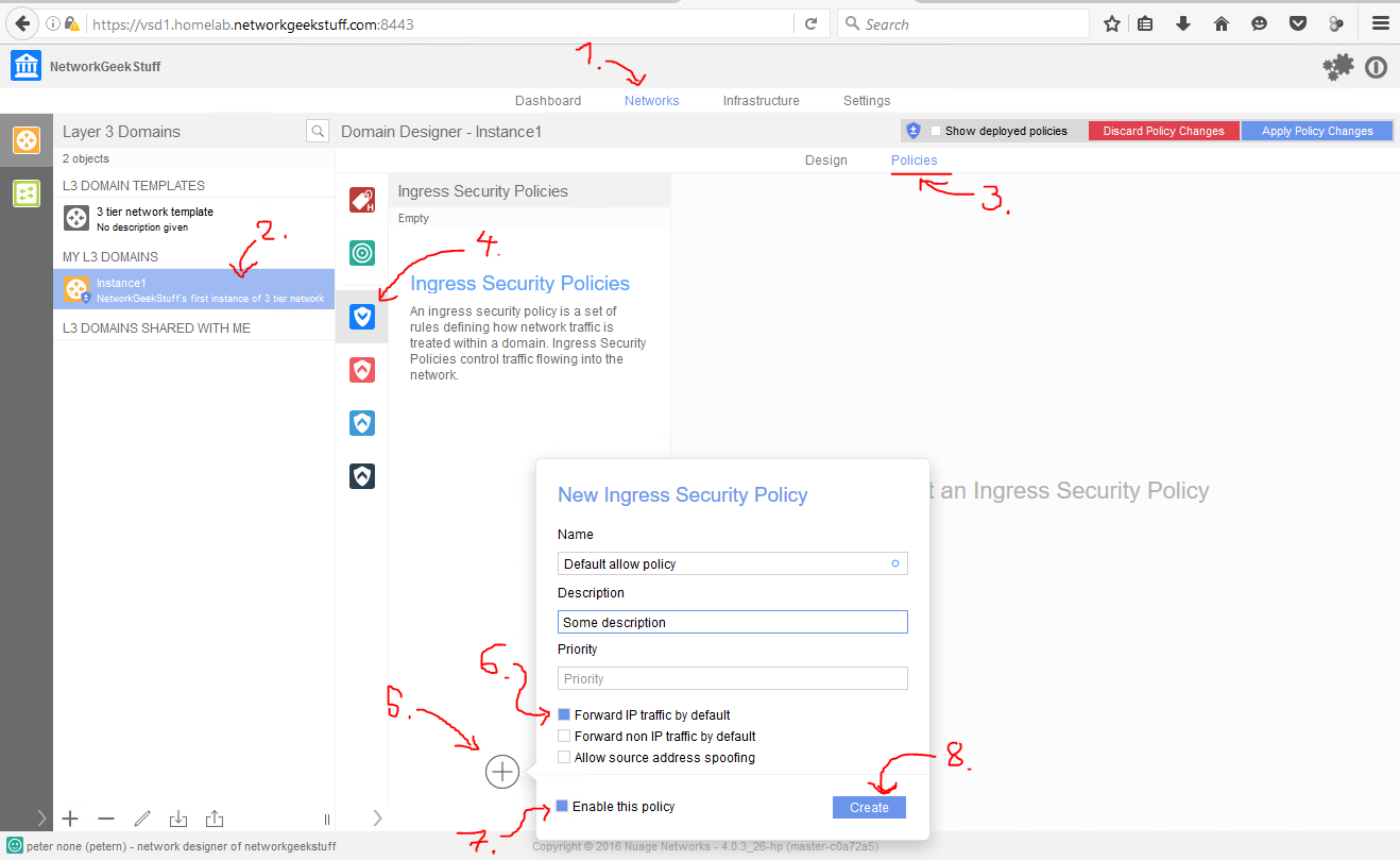
The moment you hit apply on this policy, the ping test between VMs will start working.
Step 8.2 Advanced Ingress/Egress Policies
I am going to dissapoint you right now and will not cover the advanced policies now. In summary HPE DCN supports filters between zones / domains and even individual VMs, it also can do “reflexive” policies that partly simulates a statefull firewall (but again this is only like reflexive access-lists you maybe know from Cisco, it tracks TCP/UDP ports but doesn’t really track flags or sequence numbers and as such are not a replacement for a real firewall!). I will definitelly dedicate much more space to Ingress/Egress Policies in next parts of this series, but for now I recommend you read the user guide on HPE DCN to find more if you want to.
Step 9. (Optional) Homework VRS/VSC Verifications
Right now you are able to install HPE DCN, and experiment yourself. What I really recommend next is to go to VSC and VRS instances and try to explore their CLIs for low level information how your overlay network is mapped to underlay and how your pings are really forwarded over your network. So as homework I am going to leave you with a set of best VSC and VRS commands to try.
VSC
- show vswitch-controller vsd
- show vswitch-controller vswitch
- show vswitch-controller virtual-machines
- show vswitch-controller virtual-machines enterprise “NetworkGeekStuff”
- show vswitch-controller vports type vm enterprise “NetworkGeekStuff”
- show vswitch-controller ip-routes enterprise “NetworkGeekStuff” domain “Instance1”
- show vswitch-controller vports vport-name <vportname> acl ingress-security
- show vswitch-controller vports vport-name <vportname> acl egress-security
- show vswitch-controller <generally anything behind this command is of interest>
Note: On VSC you will find two different numbers for L3 domain instance, one is VPRN and another is EVPN. The VPRN is technically a VRF (or VPN-INSTANCE in HPE terminology) that your L3 instance logically creates and EVPN is technically a L2 VS (virtual switch instance), since VSC is practically a router you can see details about this VPRN (really “VRF”) and EVPNs using commands like:
- show service id <VPRN number> base
- show service id <EVPN number> base
- show vswitch-controller ip-routes enterprise “NetworkGeekStuff” domain “Instance1”
VRS
- ovs-vsctl show
- ovs-appctl vm/show
- ovs-appctl vm/port-show <VM UUID from previous command>
- ovs-appctl bridge/acl-table
- ovs-appctl vm/dump-flows <VM UUID from previous command>
- ovs-appctl evpn/mac-table <VM UUID from previous command>
- ovs-appctl bridge/dump-flows alubr0
- ovs-dpctl dump-flows
Summary
After completing this lab, you should know how to do basic topology in HPE DCN (or Nokia’s Nuage SDN) and together with previous part 1 know how to install it in your lab.
In next parts I plan to extend on this lab to create more redundancy (adding redundant VSCs and VSDs) and then go into configuring Nuage via REST API and maybe do some outage scenarios. Stay tuned for more coming soon!
Index of article series:
- HPE’s DCN / Nuage SDN – Part 1 – Introduction and LAB Installation Tutorial
- HPE’s DCN / Nuage SDN – Part 2 – First Steps Creating Virtual/Overlay Customer Network
- HPE’s DCN / Nuage SDN – Part 3 – REST API introduction
Just mind blowing ! Never seen such a good way of writing article.
The best thing is that you have never assumed that the target audience are networking geek. Which made the article simple and elaborate.
Thanks !
Waiting for REST API article 🙂
The question is how do we troubleshoot that in real situation.
Does the good old tcpdump still works ?
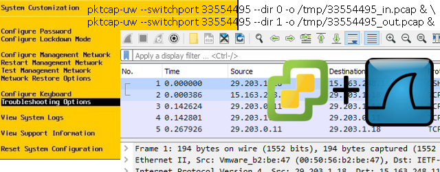
Well, yes. But since here you are playing on multiple virtual layers, you might have to be carefull where and what you are capturing with it. Endpoint VMs of course would see their traffic comming/leaving with tcpdump, but much more interesting is to login to the VRS component, which is practically just a linux box with an OpenvSwitch that has one outgoing master interface where you can tcpdump VXLAN encapsulated traffic of all the VMs hosted by the local hypervisor (VXLANs are not encrypted, so wireshark reading them is easy) or there are dynamically created small sub-interfaces for reach VM.
However much more powerfull, and I would argue needed for traoubleshooting this in production is to learn OpenvSwitch troubleshooting commands like:
watch ovs-appctl dpif/dump-flows alubr0
ovs-dpctl dump-flows
I am working on part IV of this series that will be about HW VTEPs and troubleshooting, just struggling to find enough time to finish it properly.
Thanks for the information.
I am attempting to create a script to monitor VSD clusters where an automated alert would be generated if the cluster was to fail.
Do you know how this may be possible through scripting? If so can you share a link to any references that may provide insights for me pls?
Thank you,