


Cisco IOS XR – Complete Getting Started Examples Guide, Part 2/2
Following previous part 1 article of this IOS XR guide that presented basic examples for IOS XR on most CCNA level technologies, this post will continue and give the basics of FHRP, MPLS, BGP and some minor features like route redistribution to finalize this two article series. Again the aim is not to explain in detail the protocols or theory behind them, only to provide quickly searchable reference guide to quickly configure these protocols on IOS XR. This is the second and final part of this “Getting Started Example Guide”, next for IOS XR I will continue in a separate articles that will go to specific advanced topics independently.
Content of this article:
1. First Hop Redundancy Protocols on IOS XR
   - Hot Standby Router Protocol (HSRP)
   - Virtual Router Redundancy Protocol (VRRP)
   - Gateway Load-Balancing Protocol (GLBP)
2. Redistribution on IOS XR
   - Redistribution into IS-IS
   - Redistribution into OSPF
3. Basic MPLS configuration on IOS XR
4. Basic BGP configuration on IOS XR
Contents of Article
First Hop Redundancy Protocols
Lets start with the most simple part. First Hop Redundancy Protocols are protocols that allows you to make your default gateway IPv4 virtual and redundant on two separate routers. In cisco routers, we have three of these protocols and for each a quick example is visible below. But before that lets quickly go via the IPv4 and IPv6 support on different platform.
FHRP Protocol      Cisco IOS/IOS XE Software       Cisco IOS XR Software
HSRP               IPv4, IPv6 (with version 2)     IPv4
VRRP               IPv4                            IPv4, IPv6
GLBP               IPv4, IPv6                      Not supported
Hot Standby Router Protocol (HSRP)
HSRP is a cisco proprietary protocol for gateway IP redundancy. In the following picture, you have very simple topology with both IOS XR and IOS routers and their configuration.
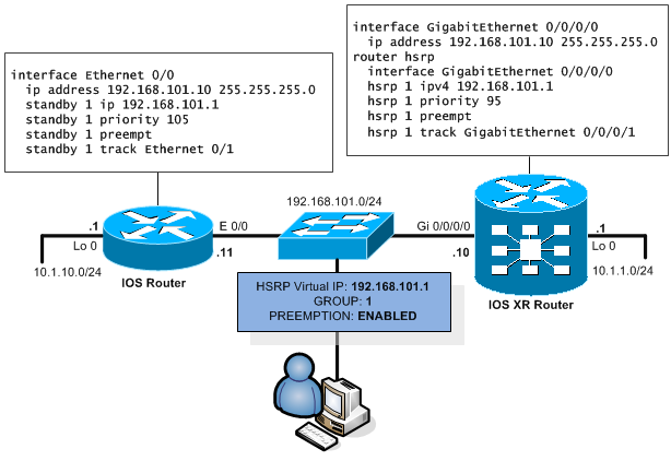
Explanation is quite simple, HSRP routers broadcast their virtual-IP, priority and HSRP group ID on multicast IP 224.0.0.2 in UDP packets port 1985. With this broadcast, they locate each other and the router with highest priority wins and starts to actively serve the packets leaving vie default gateway. HSRP has hello interval of 3 seconds and hold down timer of 10 seconds.
The configuration is as follows on IOS:
interface Ethernet 0/0
  ip address 192.168.101.10 255.255.255.0
  standby 1 ip 192.168.101.1
  standby 1 priority 105
  standby 1 preempt
  standby 1 track Ethernet 0/1
Configuring HSRP you have to start with a unique ID called HSRP group that is a value “standby <ID>” from 1 to 255 and has to be unique in a broadcast domain of the given interface. If you want to have multiple groups on an interface you can make the commands unique based on this HSRP group. Second value is priority that is also a value from 1 to 255. By default the priority is 100 and higher value wins.
Preemption is by default disabled, this means that by default if your master fails, the backup router becomes a master. However when the master recovers, he will not assume the role of the new master until the current master fails despite the priority value. If you want the highest priority router to become master in any situation, you have to activate the preemption with the standby <ID> preempt command.
Last part is the ability to track another interface and/or tracking object. This is used for gateway routers in a situation when an outgoing uplink interface like Ethernet 0/1 fails on the current active master. In this situation the master is no longer the best router to be the gateway as he has no uplink. Therefore using tracking the current master can decrease its priority dynamically and allow another router to be the new master.
On IOS XR, it is a little bit different in a sense that the configuration commands have moved to a common “router hsrp” section in the configuration. But as you see, there is nothing new to explain compared to IOS configuration.
The configuration of HSRP on IOS XR is as follows:
interface GigabitEthernet 0/0/0/0
  ip address 192.168.101.10 255.255.255.0
router hsrp
  interface GigabitEthernet 0/0/0/0
  hsrp 1 ipv4 192.168.101.1
  hsrp 1 priority 95
  hsrp 1 preempt
  hsrp 1 track GigabitEthernet 0/0/0/1
Verification on IOS:
Router# show standby brief
                     P indicates configured to preempt.
                     |
Interface   Grp  Pri P State   Active      Standby     Virtual IP
Gi0/0/1     1    105 P Active  local       192.0.2.3   192.0.2.1
Verification on IOS XR
RP/0/RSP0/CPU0:Router# show hsrp
Wed Aug 17 13:51:31.032 UTC
                        P indicates configured to preempt.
                        |
Interface   Grp    Pri  P State     Active addr    Standby addr   Group addr
Gi0/0/0/1   1      95   P Standby   192.0.2.2      local          192.0.2.1
Virtual Router Redundancy Protocol (VRRP)
The RFC standard protocol for default gateway redundancy. Again the initial example of VRRP deployment with both IOS and IOS XR routers. It is using multicast address of 224.0.0.18 when running in IPv4.
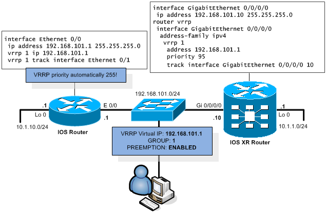
Explanation is again quite simple, VRRP routers broadcast their virtual-IP, priority and VRRP group ID on multicast IP 224.0.0.18. With this broadcast, they locate each other and the router with highest priority wins and starts to actively serve the packets leaving vie default gateway. VRRP has 1second advertisement timer and hold down timer below 4seconds.
The configuration is again very simple for both IOS and IOS XR as shown below.
Configuration of VRRP on IOS:
interface Ethernet 0/0
  ip address 192.168.101.1 255.255.255.0
    vrrp 1 ip 192.168.101.1
    vrrp 1 track interface Ethernet 0/1
The configuration concept of VRRP is again very similar to the HSRP. You need to configure VRRP group ID in a range from 1 to 255 that is unique in the L3 broadcast domain. There is also priority to configure in range from 1 to 254 that is by default 100, but if the physical IP is the same on an interface as the Virtual IP, the router automatically assumes the role of permanent VRRP master with 255 priority (255 is reserved for this situation when you configure HSRP virtual IP the same as physical interface IP). This permanent VRRP master is called VRRP owner.
VRRP is by default in preemption mode but you can disable it with using “no vrrp 1 preempt” if needed. Interface and object tracking is supported in the same way as on HSRP.
Configuration of VRRP on IOS XR:
interface GigabitEthernet 0/0/0/0
  ip address 192.168.101.10 255.255.255.0
router vrrp
  interface GigabitEthernet 0/0/0/0
    address-family ipv4
      vrrp 1
        address 192.168.101.1
        priority 95
        track interface GigabitEthernet 0/0/0/0 10
On IOS XR, the configuration is moved to the router vrrp section and also for the support of IPv4 and IPv6 divided under the address-family sections.
Verification
On IOS, VRRP verification can be done with show vrrp brief:
Router# show vrrp brief
Interface    Grp Pri Time  Own Pre   State   Master addr     Group addr
Ethernet0/0    1 95  3223      Y     Backup  192.168.101.11  192.168.101.1
On IOS XR, VRRP verification can be done with show vrrp:
RP/0/RSP0/CPU0:Router# show vrrp
Thu Aug 29 02:33:00.888 UTC
IPv4 Virtual Routers:
                           A indicates IP address owner
                           | P indicates configured to preempt
                           | |
Interface       vrID Prio  A P State    Master addr   VRouter addr
Gi0/0/0/0          1 105     P Master   local         192.168.101.1
Gateway Load Balancing Protocol (GLBP)
This cisco proprietary protocol is actually my favorite protocol of all FHRP protocols simply because it does load-balancing for all the physical routers that make the GLBP group while all the hosts still think they use a single IP gateway. The trick is that there is still an active GLBP router selected based on priority, but there are not virtual MAC addresses and only the active GLBP router replies to ARP requests on the virtual IP with mac addresses of all the GLBP group members in round-robin fashion (although it is possible to configure each router with weight and with it statistically put more ARP responses to different routers in a group).
GLBP protocol use 224.0.0.112 as a multicast IP in IPv4 network and GLBP is using group ID as the other protocols but with range from 1 to 1023. Priority by default 100, with range 1 to 255. Hello timer 3, hold down timer 10 seconds. Preemption is not enabled by default.
However, GLBP is not supported on IOS XR, so the following example is for IOS routers only.
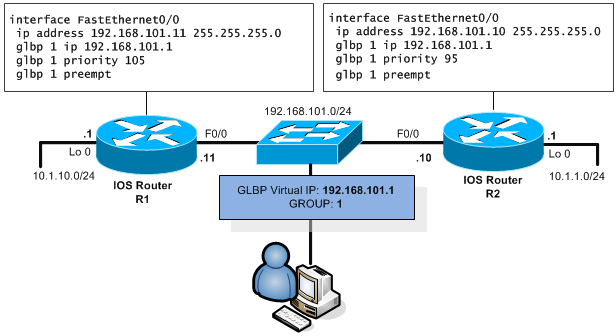
The configuration example of GLBP on IOS is as follows (router R1 perspective):
interface FastEthernet0/0
 ip address 192.168.101.11 255.255.255.0
 glbp 1 ip 192.168.101.1
 glbp 1 priority 95
 glbp 1 preempt
IPv6 example bonus:, if you like, here is a quick modification for IPv6 auto-configured version of GLBP on IOS:
interface fa0/0
 ipv6 address 2002:8:101:1::/64 eui-64
 glbp 1 ipv6 autoconfig
 glbp 1 preempt
Verification
For a single GLBP configured Virtual IP, you can see multiple lines of output in the show glbp brief. This shows you not only the VirtualIP, but also all the members of the group doing the forwarding.
R1#show glbp brief
Interface   Grp  Fwd Pri State    Address         Active router   Standby route
Fa0/0       1    -   100 Standby  192.168.101.1   192.168.101.11  local
Fa0/0       1    1   7   Listen   0007.b400.0101  192.168.101.11  -
Fa0/0       1    2   7   Active   0007.b400.0102  local           -
Inter-Protocol Redistribution
Often you encounter a network that for various (mostly historical) reasons have more than one routing protocol implemented, it is often needed to allow a single route to exist in both protocols. To achieve this, the solution is to redistribute a route from the protocols it was sourced in to the other protocols. Very importantly you have to take care of the differences of the two protocols to not create more problems (mostly loops) than benefit from redistribution.
Redistribution into IS-IS
First protocol we will mention is IS-IS (as my favorite). I will show you a very basic example how to configure redistribution. For those who know IOS redistribution, this will be well known only on IOS XR, the command has a bit different placement.
The redistribution command is inside the address-family ipv4 unicast and in our example, we give redistributed routes metric 20. However, by default the seed metric for redistributing to IS-IS in Cisco routers (IOS + IOS XR) is 0.
router isis 1
 net 49.0000.0100.0200.0300.00
 address-family ipv4 unicast
  redistribute ospf 1 metric 20
 interface GigabitEthernet0/0/0/0
  address-family ipv4 unicast
!
router ospf 1
 area 0
  interface GigabitEthernet0/0/0/1
For reference, this is how the redistribution would look like on IOS:
router isis 1
 redistribute ospf 1 metric 20
Verification
For quick verification, you can simply check the routing table as shown below, please not that IS-IS redistributed routes are not marked in any special way:
RP/0/RSP0/CPU0:IOSXR# show route
Wed Jan 05 11:12:24.092 UTC

Codes: C - connected, S - static, R - RIP, B - BGP
       D - EIGRP, EX - EIGRP external, O - OSPF, IA - OSPF inter area
       N1 - OSPF NSSA external type 1, N2 - OSPF NSSA external type 2
       E1 - OSPF external type 1, E2 - OSPF external type 2, E - EGP
       i - ISIS, L1 - IS-IS level-1, L2 - IS-IS level-2
       ia - IS-IS inter area, su - IS-IS summary null, * - candidate default
       U - per-user static route, o - ODR, L - local, G - DAGR
       A - access/subscriber, (!) - FRR Backup path

Gateway of last resort is not set
i L2 10.1.10.0/24 [115/20] via 192.168.101.11, 00:00:35, GigabitEthernet0/0/0/1
i L2 10.1.1.0/24 [115/30] via 192.168.102.10, 00:21:46, GigabitEthernet0/0/0/0
Redistribution into OSPF
When redistributing into OSPF, by default the metric is type E2*, default seed metric from IGP is 20 and from BGP is 1. Also IOS and IOS XE router by default redistribute only classfull networks (you have to use “subnets” keyword).
*E1 vs E2 types. E2 metric when given to external route will not be incremented when propagated in internal network after being given initial seed metric. E1 on the other hand is incremented in addition to the initial seed metric as any other OSPF route on every hop.
The configuration is not that different in comparison to older IOS redistribution, in the following example we will redistribute IS-IS to OSPF.
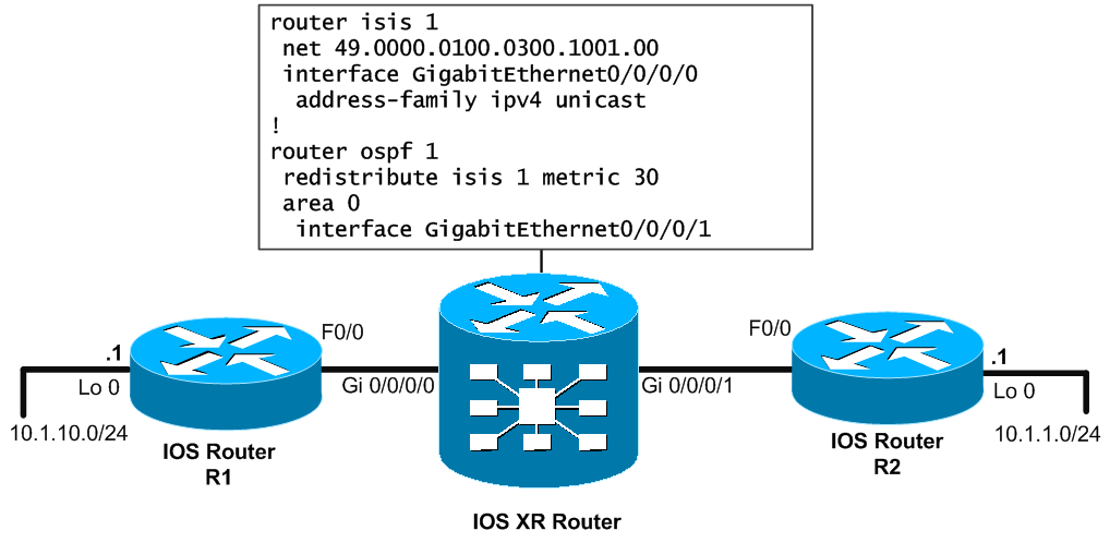
Cisco IOS and IOS XE (for reference):
router ospf 1
 redistribute isis 1 subnets metric 30
Note that this command will redistribute routes (also classless subnets thanks to the “subnets” word) with default E2 (non-incrementing one) metric 30.
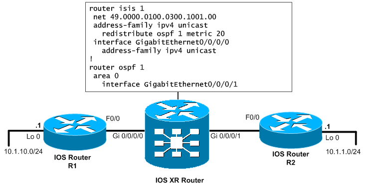
Cisco IOS XR:
router isis 1
 net 49.0000.0100.0300.1001.00
 interface GigabitEthernet0/0/0/0
  address-family ipv4 unicast
!
router ospf 1
 redistribute isis 1 metric 30
 area 0
  interface GigabitEthernet0/0/0/1
Note that you do not have to use the “subnets” keyword on IOS XR to redistribute also classless networks.
Verification
Also on the verification front, the routing table looks very familiar on IOS XR:
RP/0/RSP0/CPU0:IOSXR# show route
Wed Jan 6 13:02:20.923 UTC

Codes: C - connected, S - static, R - RIP, B - BGP
       D - EIGRP, EX - EIGRP external, O - OSPF, IA - OSPF inter area
       N1 - OSPF NSSA external type 1, N2 - OSPF NSSA external type 2
       E1 - OSPF external type 1, E2 - OSPF external type 2, E - EGP
       i - ISIS, L1 - IS-IS level-1, L2 - IS-IS level-2
       ia - IS-IS inter area, su - IS-IS summary null, * - candidate default
       U - per-user static route, o - ODR, L - local, G - DAGR
       A - access/subscriber, (!) - FRR Backup path

Gateway of last resort is not set

O E2 10.1.10.0/24 [110/30] via 192.168.101.11, 00:00:19, GigabitEthernet0/0/0/0
O    10.1.1.0/24 [110/20] via 192.168.102.10, 00:15:06, GigabitEthernet0/0/0/1
Multiprotocol Label Switching (MPLS)
Now this one is a kicker. Actually this technology is like an elephant in a room that nobody mentions, but all know it is there. MPLS has become the major player in all bigger ISP networks with its marvelous benefits that it gives. I personally like to say that the benefits of MPLS are not in any speed or other things, but it did to networks the same that Virtualization did to computers. Also it had returned the long missed (since ATM times) Traffic Engineering back to the IP networks.
In this quick overview, I will not mention anything from MPLS theory, if there is someone reading this without any prior knowledge about MPLS, then I would ask him to stop on this point and go read some theory basics of MPLS before continuing here.
MPLS configuration
Let’s first give you my lab topology to have you orient in it.
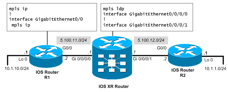
On older IOS and IOS XE platforms, you simply enable MPLS globally with “mpls ip” in global configuration and then enable all the interfaces that you want to participate in the MPLS cloud with “mpls ip” under the configuration context of each interface. This will start for you the basic MPLS (take not that on very old IOS routers, this might activate older MPLS label distribution protocol called TDP).
mpls ip
!
interface GigabitEthernet0/0
 mpls ip
On newer IOS XR, it is a bit other way around when you put the interface under mpls ldp configuration context.
mpls ldp
 interface GigabitEthernet0/0/0/0
 !
 interface GigabitEthernet0/0/0/1
Verification
Well, once you activate MPLS and LDP protocol on two routers on their interconnecting interface, you should get LDP neighbourship comming up (you get SYSLOG message about this to the console). To verify your neighbours on IOS XR, you can execute show mpls ldp neighbor.
RP/0/RSP0/CPU0:IOSXR# show mpls ldp neighbor
Peer LDP Identifier: 5.100.12.2:0
  TCP connection: 5.100.12.2:23307 - 5.100.12.1:646
  Graceful Restart: No
  Session Holdtime: 180 sec
  State: Oper; Msgs sent/rcvd: 27/26; Downstream-Unsolicited
  Up time: 00:06:28
  LDP Discovery Sources:
    GigabitEthernet0/0/0/1
  Addresses bound to this peer:
    10.1.1.1 5.100.12.2
Secondly, you see if the other neighbors are sending you MPLS tag bindings. These are numerical labels used for forwarding and there is always your (as of from the perspective of every router) internal label generated for a particular prefix and also all your neighbor will send you their label for the same prefix. Of course you will send them your local prefix as well.
For example on the following example we see an internal label 21 for a prefix 10.1.1.0/24 and also the label 24 that your neighbor has assigned to the same prefix.
RP/0/RSP0/CPU0:IOSXR# show mpls ldp bindings
<…output omitted…>
10.1.1.0/24, rev 24
        Local binding: label: 23
        Remote bindings: (2 peers)
           Peer Label
           ----------------- --------
           10.1.1.0:0        24
           10.1.11.0:0       25
Note a very similar verification is possible on IOS routers. First the LIB:
IOSRouterR2#show mpls ldp bindings
  tib entry: 10.1.1.0/24, rev 3
        local binding:  tag: imp-null
        remote binding: tsr: 5.100.12.1:0, tag: 23
And also then you can have a look on the LFIB:
IOSRouterR1#show mpls forwarding-table
Local  Outgoing    Prefix            Bytes tag  Outgoing   Next Hop
tag    tag or VC   or Tunnel Id      switched   interface
21     23          10.1.1.0/24       0          Ge0/1      5.100.11.1
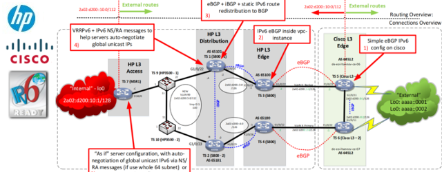
Basic BGP configuration
Ok, CCNA level of BGP is absolutely minimal, what I will show in the following example is only to start the BGP process, establish and verify neighborship and propagate some local prefix. To be more precise, we will build a simple eBGP and iBGP sessions on both IPv4 and IPv6 used for neighborship, but configure the routers to use IPv4 neighborship to exchange only IPv4 prefixes and to use IPv6 neighborship to carry only IPv6 prefixes (because you can carry both IPv4 and IPv6 on any type of underlining neighborship).
Full topology with all configuration at glance below:
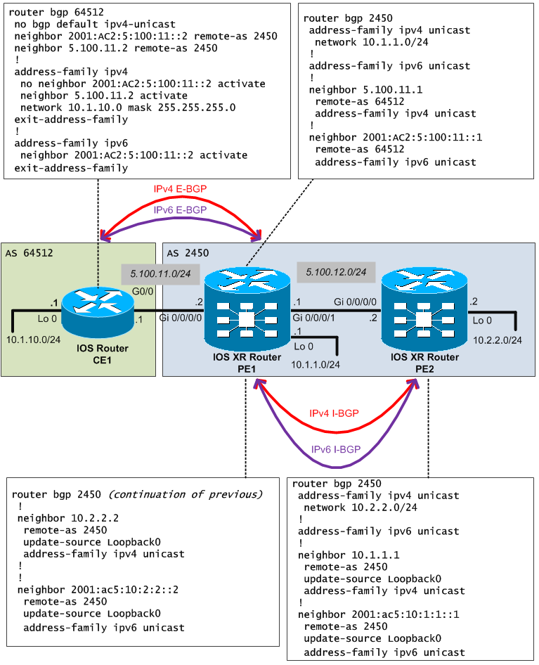
If you know the older IOS configuration of BGP, the IOS XR should be no problem for you. The only difference in basic configurations is that now you create address-families under neighbors and not neighbors under address-families like in IOS.
Now lets go through the configuration, first the IOS part:
router bgp 64512
 no bgp default ipv4-unicast
 neighbor 2001:AC2:5:100:11::2 remote-as 2450
 neighbor 5.100.11.2 remote-as 2450
 !
 address-family ipv4
  network 10.1.10.0 mask 255.255.255.0
  no neighbor 2001:AC2:5:100:11::2 activate
  neighbor 5.100.11.2 activate
 exit-address-family
 !
 address-family ipv6
  neighbor 2001:AC2:5:100:11::2 activate
 exit-address-family
The configuration is simple, you create two peers (the same neighbor router over IPv4 and IPv6) and activate corresponding address-family propagation only for IPv4 to the IPv4 neighbor and IPv6 only to the IPv6 neighbor.
You might notice there is something different here than you are probably used to and that is that I have disabled the default IPv4 prefix propagation in the default bgp context with no bgp default ipv4-unicast. This disables the default IPv4 prefix propagation and forces you to use IPv4 address-family if you want it. This helps to have much more control over BGP. Let me give you example of the exact same configuration (for IPv4 prefixes only) to show you what I mean.
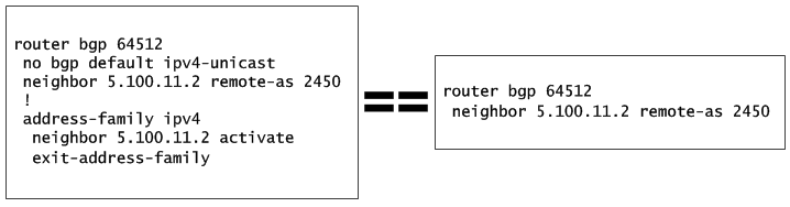
The IOS XR part is more interesting in that the guys in Cisco reversed the order of configuration context. Instead of creating neighbors under address-families like on IOS, on IOS XR you add address-families under neighbor creation. Other than that, I believe there no more explanation needed to the config below. Additionally, notice that the network advertisement stayed the same with the network command but the format changed utilizing the /24 for mask.
router bgp 2450
 address-family ipv4 unicast
  network 10.1.1.0/24
 !
 address-family ipv6 unicast
 !
 neighbor 5.100.11.1
  remote-as 64512
  address-family ipv4 unicast
 !
 neighbor 2001:AC2:5:100:11::1
  remote-as 64512
  address-family ipv6 unicast
!
 neighbor 10.2.2.2
  remote-as 2450
  update-source Loopback0
  address-family ipv4 unicast
 !
 neighbor 2001:ac5:10:2:2::2
  remote-as 2450
  update-source Loopback0
  address-family ipv6 unicast
OPTIONAL: BGP authentication configuration
Under IOS, we go the usual way like this:
router bgp 64512
  neighbor 5.100.11.2 remote-as 2450
  neighbor 5.100.11.2 password BGP_password
On IOS XR, as with most thing you have to go under the neighbor context and add the password there:
router bgp 64500
  neighbor 5.100.11.1
    remote-as 64512
    password clear BGP_password
    address-family ipv4 unicast
Verification
To verify that BGP is up and running you can check the BGP table to see the neighbors listed and the number of prefixes they are sending to you in the St/PfxRcd field. You can also notice the AS number for each neighbor.
RP/0/RSP0/CPU0:IOSXRPE1#sh bgp table ipv4 unicast
Tue Jan 8 9:09:25.011 UTC
Neighbor       VRF         Spk   AS     TblVer  InQ OutQ  St/PfxRcd
5.100.11.1     default     0     64512  12      0   0     1
10.2.2.2       default     0     2450   12      0   0     1
Also this is possible for the other address-families, but in IPv6 we do not yet have any prefixes propagated.
RP/0/RSP0/CPU0:IOSXRPE1#sh bgp table ipv6 unicast
Tue Jan 8 9:10:12.149 UTC
Neighbor                 VRF       Spk  AS      TblVer InQ OutQ  St/PfxRcd
2001:ac5:5:100:11::1     default   0    64512   12     0   0     0
2001:ac5:10:2:2::2       default   0    2450    12     0   0     0
Summary
Ok, I perfectly understand that this overview only scratched the surface of far more advanced topics as BGP and MPLS, but the intention here was not to go deep. More advanced things will come only when I get my hand on some more IOS XR routers (as I plan to start learning to move my CCIP certification to CCNP SP replacement). So I believe there will be some more BGP and MPLS articles coming to networkgeekstuff.com in the near future.
Excellent quick and dirty guide. Thanks a mil
Hi, good work! What about extending the guide torwards ios xr and stub/nssa? I’m wondering about if there is any implementation of “translate type7 suppress-fa” in ios xr. Any idea?
Hello Inschurk,
Sorry I didn’t went into much details with every protocol. I do not even have any IOS XR available anymore to have a look for what you would like. I think you should check cisco documentation for that.
FYI, our test IOS XR didn’t entered production as we went decided to go with a vendor with better price for port/bandwidth compared to Cisco. Do not get me wrong, I think the Cisco IOS XR are a very nice machines, but sometimes going with Cisco doesn’t make sense financially. When I get my hands on IOS XR next time, I hope I will have more time to play with them (or get them in production environment as this quick/dirty guide was written in a lab).
Peter
This is helping me to configure Ist time asr9006.
thanx to all
great .
I’m thinking about something roughly like this this. If i get going I’ll have
to remember to come back to this page and see if there’s any
updates.
Very useful and well planned document.Is very good.