Configuring MPLS L3 VPN on IOS XR
MPLS L3 VPN are a common standard in every bigger ISP or Datacenter for many years now and most of us know the basic principles and have experience configuring this on a normal Cisco IOS routers. But what about the new IOS XR? Well, some of us have real experience, some of us do not. Myself, I have long had only theoretical knowledge of MPLS L3 VPNs on IOS XR and I have finally get my hand on IOS XR to try it and with this article, I will get together basic configuration for quick reference also to you.
Contents
MPLS L3 VPN principles (again)
To get you a very quick start with the MPLS concept before the configuration, let me start with a basic of theory. MPLS started as a great technology to not only make switching more effective, but also it enabled with its Label Switched Paths (LSP) a way to tunnel traffic between two endpoints. The nodes (routers) in the middle of this LSP didn’t have to look at the IP header being tunneled and therefore the IP header can be effectively hidden as a side effect.
With this came another idea when someone realized that you can create a VPN service with this simple and native tunneling mechanism. This kind of VPN is called “peer-to-peer VPN“, and despite the name, do not confuse it with classical point-to-point tunnels like IPSec or L2TPv2. These older technologies are called “overlay VPNs“.
What this means is that you can interconnect multiple customers by putting them to an MPLS L3 VPN. Communicate and route their networks and thanks to tunneling and virtualization, the customer can even have conflicting subnets and there will never be a collision inside the MPLS. Below picture shows in principle the MPLS L3 VPN with two VPNs that are called “CUSTOMER_A” and “CUSTOMER_B”.
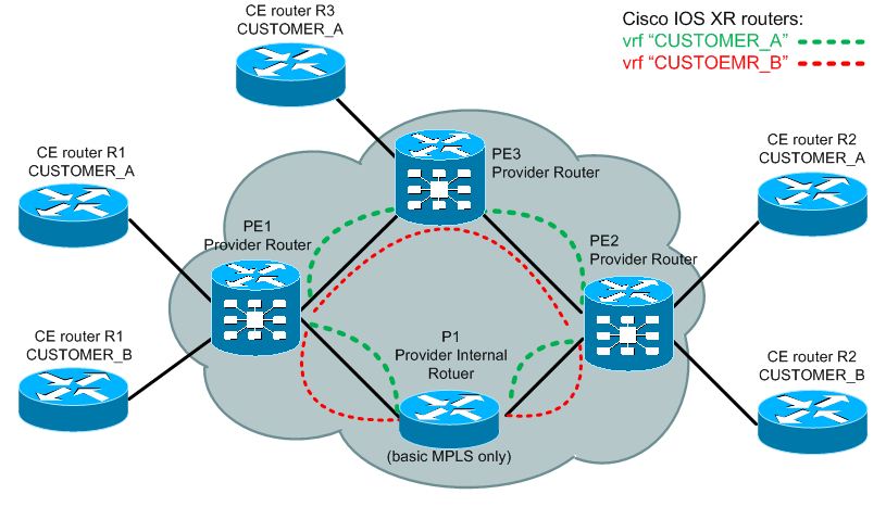
The last parts of this puzzle are router virtualization and MP-BGP. Router virtualization is the same thing when you are running VMWare or Virtualbox on your PC, only that the router will spawn internal virtual routers that are in Cisco world called Virtual Routing and Forwarding (VRF) and you can assign physical or logical interfaces to this VRF to act independently. It is similar idea than a VLAN on layer 2 that is dividing switch ports to several virtual switches. The second is BGP protocol extension called Multip-Protocol BGP (MP-BGP). This is a BGP extension that allows non-IPv4 prefixes to be propagated by BGP. We will use this protocol to distribute IPv4 prefixes, but inside visualization they have to be modified by extending them with something called Route-Distinguisher (RD). RD is 64bit number that is added to the 32 bits of IPv4 prefix and together create a new address family called VPNv4. This help the MPLS L3 VPN cloud to not mix prefixes of different VPNs inside MP-BGP propagation as it is expected every VPN will have a unique RD.
One additional thing to mention is the Route Target (RT), this has identical representation as RD in that it is a 64bit number, but this provides additional filtering between MP-BGP propagation and import/export of VPNv4 prefixes to/from a specific VRF. For example, by default you can simple create a unique RT for both import/export for every customer and this filter will only allow the routes of the same customer/vpn to only be imported/exported to the correct VRF. But if you need for example to have a common network area that is shared by two or more customers, you can create another VRF and import this to multiple customer VRFs by defining new combination of import/export RTs. This however is a bit advanced concept so feel free to read forward as the example below will present a simple MPLS network with a shared VRF environment.
In fact, if you do not have much theory background, visit my previous article that is MPLS VPN tutorial with configuration example for HP A-Series (H3C). You do not have to read it full if you are not interested in HP devices, but the theory is there in more detail.
MPLS L3 VPN configuration explanation on IOS XR
So what configuration parts do you need to configure MPLS L3 VPN on an IOS XR? Here is a quick “todo” list:
0) Prerequisite: Have a working MPLS cloud
1) Create VRF with unique RD, import/export RT and interfaces.
2) Create BGP and MP-BGP sessions between PE routers
3) Create PE to CE communication inside a VRF context and redistribute between VRF and MP-BGP
Step 0) Prerequisite
This guide assumes you have an MPLS network configured (minimum MPLS activated/running, internal IGP protocol and LDP sessions established). This configuration I have already presented as part of older article on basic IOS XR configuration: Cisco IOS XR – Complete Getting Started Examples Guide – Part 2/2.
Step 1) Create a VRF
This is a simple step and just follow the syntax below:
!Assign a VRF name:
RP/0/RP0/CPU0:router(config)# vrf vrf-name

!Enter the address-family ipv4 context menu
RP/0/RP0/CPU0:router(config-vrf)# address-family ipv4 unicast

!Specify import and export RTs:
RP/0/RP0/CPU0:router(config-vrf-af)# import route-target
                                     [asnumber:nn | ip-address:nn]
RP/0/RP0/CPU0:router(config-vrf-af)# export route-target
                                     [asnumber:nn | ip-address:nn]

!Assign one or more interfaces to the VRF
RP/0/RP0/CPU0:router(config)# interface GigabitEthernet 0/0/0/0
RP/0/RP0/CPU0:router(config-if)# vrf vrf-name
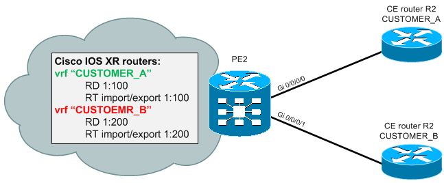
To follow the commands with an exact example, here is limited scenario with only VRF configuration:
vrf Customer_A
 address-family ipv4 unicast
 import route-target 64500:11
 export route-target 64500:11
!
vrf Customer_B
 address-family ipv4 unicast
 import route-target 64500:12
 export route-target 64500:12
!
interface GigabitEthernet0/0/0/0
 vrf Customer_A
 ipv4 address 10.1.0.1 255.255.255.252
!
interface GigabitEthernet0/0/0/2
 vrf Customer_B
 ipv4 address 10.2.0.5 255.255.255.252
After configuration, you can use show vrf detail to see your configured VRFs, example below:
RP/0/RSP0/CPU0:PE3# show vrf all detail

VRF CUSTOMER_A; RD 1:100; VPN ID not set
Description not set
Interfaces:
  GigabitEthernet0/0/0/0
Address family IPV4 Unicast
  Import VPN route-target communities:
    RT:1:100
  Export VPN route-target communities:
    RT:1:100
  No import route policy
  No export route policy
VRF CUSTOMER_B; RD 1:200; VPN ID not set
Description not set
Interfaces:
  GigabitEthernet0/0/0/1
Address family IPV4 Unicast
  Import VPN route-target communities:
    RT:1:200
  Export VPN route-target communities:
    RT:1:200
  No import route policy
  No export route policy
Step 2) Configure BPG and MP-BGP sessions
To propagate VPNv4 prefixes inside your MPLS cloude between the PEs, you have to configure first the basic BGP to every other PE router (or use route-reflectors/confederation that are not in scope of this article). Once basic BGP is configured, you can activate MP-BGP on top of the existing BGP sessions. I will not go in detail to all basic BGP configurations, if you need more BGP examples, have a look on my Cisco IOS XR – Complete Getting Started Examples Guide, Part 2, where BGP is also explained.
!First we activate BGP with:
RP/0/RP0/CPU0:router(config)# router bgp as-number

!(optional) disables the default propagation of IPv4 prefixes
!           as this is not needed for MPLS L3 VPNs
RP/0/RP0/CPU0:router(config-bgp)# no bgp default ipv4-unicast

!Activates the VPNv4 globally
RP/0/RP0/CPU0:router(config-bgp)# address-family vpnv4 unicast

!Configure a BGP neighbor
RP/0/RP0/CPU0:router(config-bgp)# neighbor ip-address
RP/0/RP0/CPU0:router(config-bgp-peer)# remote-as as-number
RP/0/RP0/CPU0:router(config-bgp-peer)# update-source interface-type interface-number

!Activate MP-BGP for VPNv4 for the specific neighbor
RP/0/RP0/CPU0:router(config-bgp-peer)# address-family vpnv4 unicast
Step 3) Configure PE to CE communication inside a VRF
You can exchange routing information between the virtual VRF router inside your PE and the CE router with most of the usual methods. You can use both static routes and also routing protocols like RIP, OSPF, IS-IS for this. To configure PE to CE communication inside only a specific VRF, you cannot however use only the normal configuration commands that you are used to. You have to bind them to the specific VRF for that particular Customer/CE router so that the routing information is only exchanged in the needed VRF context.
Static routes to CE router and VRF subnets can be created very simply by using the normal static route systax for static routes, but extending it with the VRF specification:
router static
 vrf Customer_A
  address-family ipv4 unicast
   10.0.2.0/24 192.168.0.1
What you have to do then to get this prefix propagated to the MP-BGP, is the following redistribution inside the CUSTOMER_A vrf in BGP process
router bgp 64500
 vrf CUSTOMER_A
   rd 1:100
   address-family ipv4 unicast
    redistribute static
RIPv2 can also be used to communicate with CE routers inside a VRF context.
router rip
 vrf Customer_A
  interface GigabitEthernet0/0/0/0
  !
  !What we also need to do is to redistribute the MP-BGP updates to RIP
  redistribute bgp 64500
  default-metric 5
Now we must also get the RIP information redistributed the the MP-BGP
router bgp 64500
  vrf Customer_A
    rd 64500:1
    address-family ipv4 unicast
      redistribute rip
EIGRP is another example I will show to use for communication with CE router and redistribution to both import and export VRF specific EIGRP routes to MP-BGP.
router eigrp 1
  vrf Customer_A
    address-family ipv4
      default-metric 10000 100 255 1 1500
      autonomous-system 1
      redistribute bgp 64500
      interface GigabitEthernet0/0/0/0
router bgp 64500
  vrf Customer_A
    rd 64500:1
    address-family ipv4 unicast
      redistribute eigrp 1
OSPF is another option. Here I want to state that with this configuration, all OSPF routes will appear as EXTERNAL ROUTES. This can have major implications to the routing and if you want to simulate the MPLS cloud area 0, then you need to create something called MPLS super-backbone and two MPLS PE router will create virtual OSPF neighborship over BGP called “OSPF sham link”. However this is beyond the scope of this article (maybe some other time).
router ospf 1
  vrf CUSTOMER_A
    router-id 1.1.1.1
    redistribute bgp 64500
    area 0
      interface GigabitEthernet0/0/0/0

router bgp 64500
  vrf CUSTOMER_A
    address-family ipv4 unicast
      redistribute ospf 1 [match {external [1|2] | internal}
And last possibility is that you can even have BGP session with the customer CE router. But again only from inside the VRF on the PE router.
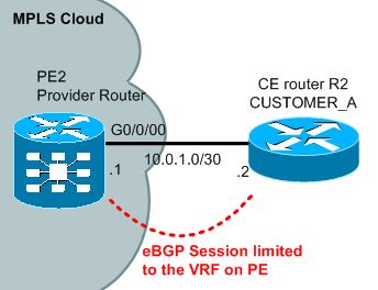
Customer CE router R2 BGP (IOS):
router bgp 65002
  neighbor 10.0.1.1 remote-as 65001
  network 10.10.10.0 mask 255.255.255.0
MPLS Cloud PE2 router (IOS XR):
router bgp 65001
  address-family vpnv4 unicast
  vrf CUSTOMER_A
    rd 1:100
    address-family ipv4 unicast
    !
    neighbor 10.0.1.2
      remote-as 65002
      update-source GigabitEthernet0/0/0/0
      address-family ipv4 unicast
You can also do some minor adjustments, for example the basic one is limiting the number of BGP session that you accept from your VPN customers to protect against DoS attacks or simply wasting resources. The command below creates such limit for 1000 routes and optionally you can specify also a warning to syslog/SNMP after reaching 75% routes and the “warning-only” option makes this limit not drop routes above the 1000, and only generate a warning.
    neighbor 10.2.1.1
      maximum-prefix 1000 [75] [warning-only]
BGP between PE and CE router and its issues
AS Override
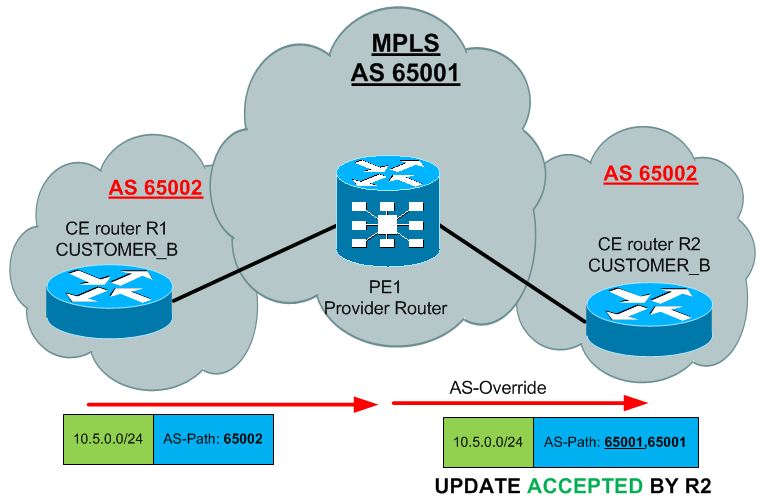
Another very common limitation with BGP is the problem that your VPN client will have the same BGP AS number used on multiple sites. This means that when the update will be crossing your MPLS network, it will be blocked when the update will be sent to second CE in different site. See below what I mean:
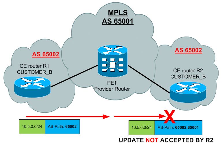
To avoid this common issue, you can tell your PE routers to modify the AS-Path by overriding the number inside. This feature replaces the customer AS number with the provider number. Configuration is very simple:
router bgp 65001
  vrf CUSTOMER_B
    neighbor 10.0.1.2
      remote-as 65002
      address-family ipv4 unicast
        as-override
With the AS path pro-actively modified to hide other customer sites, the R2 CE router can now accept the updates in our scenario.
Allowas-in
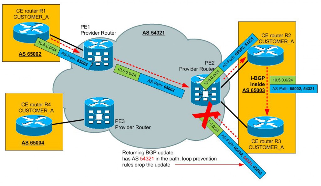
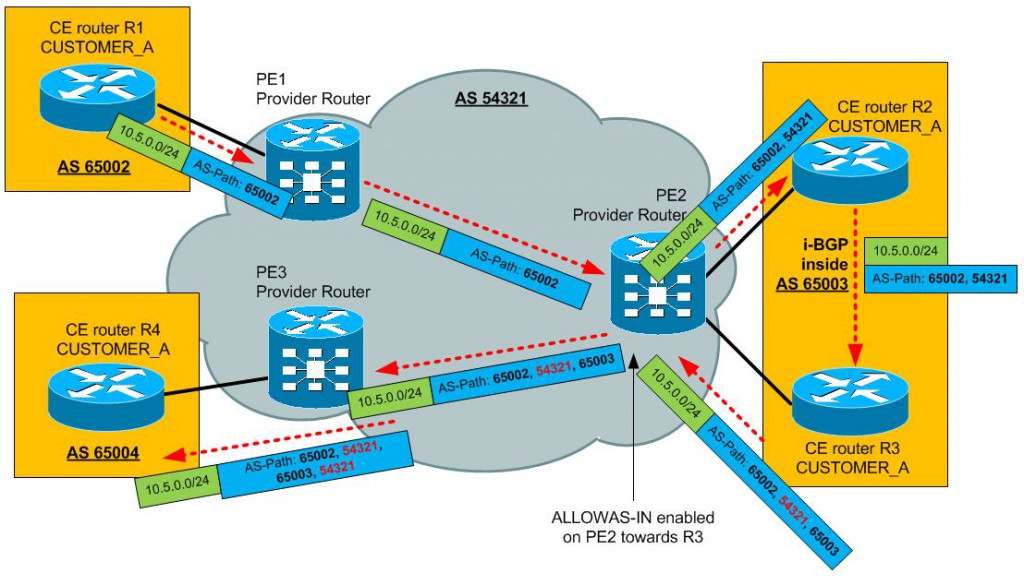
Another common issue with BGP communication is the fact the customer site can return to you an BGP update your (providers) AS inside the path. This is typically when you are trying to achieve a hub-and-spoke scenario (and you cannot avoid it). For example below, notice that the PE2 router must reject the update returning from the HUB site because it see its own AS number in the AS Path.
To enable the PE2 router to accept this, technically looped update, you can use the “allowas-in” feature. Configuration is very simple, it basically disables the looped AS check for a specific neighbor:
router bgp 1
  address-family ipv4 vrf CUSTOMER_A
  neighbor 10.0.1.2 allowas-in [number]
The optional [number] parameter enables you to specify how many local AS numbers can occur in the path, if you for example set it to 3, then the update can loop three times (AS Path still OK: 65002, 54321, 65003, 54321, 65001, 54321, 65004) before it will be considered a loop and dropped.
Implementing Site of Origin (SOO) for loop prevention
With as-override and allowas-in most of BGP loop prevention mechanisms is compromised. So an additional mechanism should be used for loop prevention. The most common is Site of Origin (SOO). This is an extended community attribute for MP-BGP VPNv4 updates that can specifically identify the particular site (or better and CE router). Configuration is very simple again, just select a unique identifier in a format of AS:nn
router bgp 1
  address-family ipv4 vrf CUSTOMER_A
  neighbor 10.0.1.2
    site-of-origin 65002:1
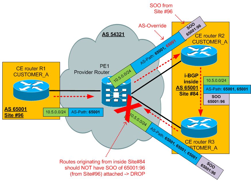
If this mechanism is configured for a particular CE (or group of CEs) and a VPNv4 route is learned with the same SOO, then this route is blocked from entering the routing table (and subsequently any other BGP update leaving the router). To demonstrate, look at the following scenario and note that for Site #96 an SOO of 65001:96 was used and for Site#84 an SOO of 65001:84 should be used.
Basic MPLS L3 verification commands list for IOS XR
To verify MPLS L3 VPN on IOS XR a quick list of the most useful commands is below. I didn’t copied also example outputs as I was personally using various topologies and I do not have a streamlined examples. However most of these commands generate an output that is very easy to understand and by following the original goal of this article to only present a quick overview, this should be enough.
#shows specific VRF routing table of CUSTOMER_A
show route vrf CUSTOMER_A

#To check what VRF specific routes are in MP-BGP
show bgp vpnv4 vrf CUSTOMER_A

#To check specifically the RD and RT being attached,
#extend the previous command with the prefix
show bgp vpnv4 vrf CUSTOMER_A 10.5.0.0 24

#To check the VRF RT and compare them to the RT attached
# to the routes, these two are best
show vrf detail
show bgp vpnv4 unicast 10.5.0.0 24

#To troubleshoot the MPLS layer inside the cloud
show cef
show cef vrf
show mpls forwarding
show mpls forwarding vrf
Summary
I really do hope that MPLS L3 VPN concepts are already well known, but giving quick and dirty overview of a few basic features and summarizing the new IOS XR configuration will have benefits for someone reading this article. Again, I hope this has been informative.









Very good article,
Think theres an error with the “Implementing Site of Origin (SOO) for loop prevention” example, because with the as-override should be 54321 and not 65001.
Awesome article and great explanation of SOO thumbs up !!!!