Rapid Ring Protection Protocol – HP Networking STP alternative?
Well, we all know STP as L2 loop-protection protocol running now in 99.9% of networks worldwide (where L2 loops are possible). HP Networking however developed a method that they hope can be a little better … I will leave the judgment of that to you and only present the Rapid Ring Protection Protocol (RRPP) in this article.
The whole idea as the name suggest is based on creating a network in “rings”. Single ring is a single loop, loop protection and transmission inside a single loop can have a good convergence time. HP elaborated on this and came with basic postulate to attack Spanning Tree Protocol: “As networks grow in size, STP takes longer and longer to converge. If we however limit every convergence to a single ring, then a single failure convergence time will still be on the same level as a single ring, despite how many rings the network is made of”. … so in summary we can create a large L2 domain made of “rings” and if there is a failure somewhere, the convergence will be only a matter of single logical ring and not affect other rings.This is interesting, but still fails to impress me as mostly I didn’t seen a L2 domain more than 6 switches in diameter in production, so Rapid STP can take care of this quite easily. On the other hand every one of these networks was designed by someone taking STP limitations into account.
HP claims that in this ring, a re-convergence is roughly about 50ms thanks to the failure notification/acknowledgment process (similar like Proposal/Agreement in Rapid STP).
Three building blocks topologies exist for RRPP shown below.
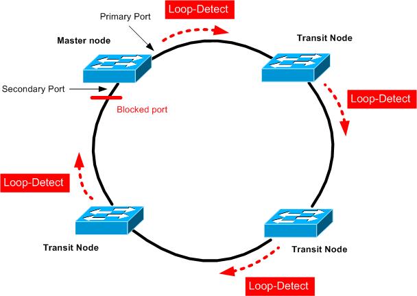
Single ring – Has only single Master and many Transit nodes.
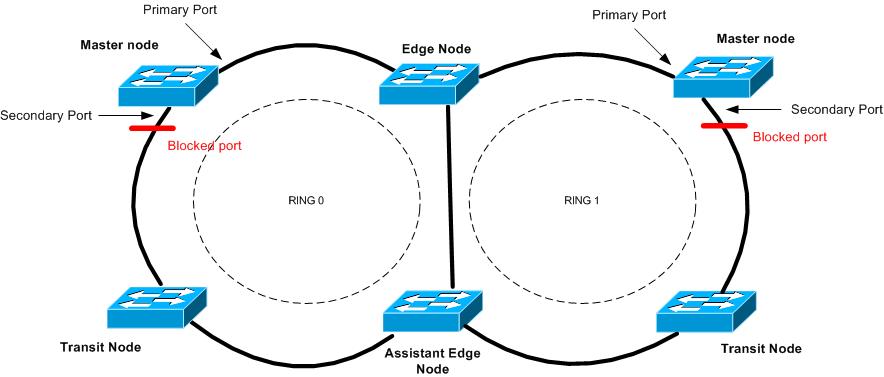
Intersecting ring – multiple rings, with a central ring that all other sub-rings connect to. The central ring is “Primary” and considered “level 0”. Secondary are considered “level 1”. RRPP protocol data units (PDUs) propagate across Level 0 and Level 1 rings differently.
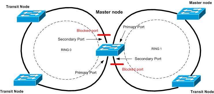
Tangent rings – Two rings that do not intersect and are this defined in separate domains utilizing the same switch or switches. This design is often used to create a load-balanced ring, where traffic can flow clockwise and counter-clockwise.
Basic ring operations
Lets take a single ring topology. In it you define a single Master (only one Master is defined in a single ring. In this ring, we have to create a “control VLAN”. this ia normal VLAN that will serve exclusively to forward control plane traffic. Then we define “Primary port” and “Secondary ports” on RRPP ring Master. The Primary port sends out loop-dectect packets and Secondary port listens for these packets arrival.
If the loop-detection packets arrive safely, the Master node switch has traffic filters on the Secondary port data VLANs and thus filtering any L2 loop in the ring topology.
Error detection has two possibilities. First, the loop-detection packets do not make it to the Secondary port in timeout and the Master considers the ring disconnected in some point. Alternative is that the node that detected any link issue will send “LINK-DOWN” message on the control VLAN notifying the Master that the ring is disconnected.
Then Master considers the ring disconnected, it will open the traffic path between his Primary and Secondary port in effort to open alternative path between all Transit nodes again. Master also sends a control message telling all Transit nodes to flush their forwarding L2 tables (mac tables if you will) on all data VLANs.
Recovery is simple again, either the loop-detection packets will start to flow again via the ring after connectivity is restored, or Transit nodes notify the Master node about the recovery. In any case when this happens, the Master filters again data VLANs on Secondary port and sends a message to flush L2 forwarding tables again in the whole ring.
Single Ring Configuration example
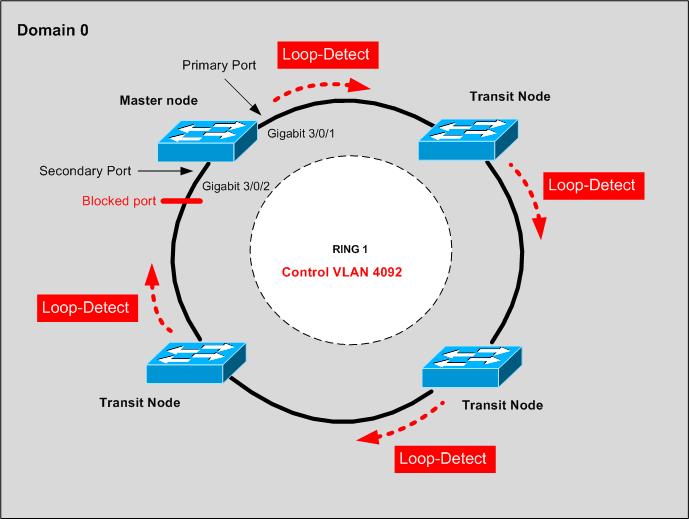
Let’s start with Single ring configuration example. We will use only single domain 0, and ring number 1. Control VLAN used will ne 4092 that cannot be used for data traffic anymore. The topology diagram is below.
And oddly enough, the first thing to configure is MSTP :). Yes, we will first do MSTP for all non-ring ports protection and also to have a starting topology. So in quick reference:
#All VLANs default to being in MSTI Instance 0. Therefore we create two MSTI instances on all devices (A,B,C,D):
revision-level 1
instance 1 vlan 1 to 500
instance 2 vlan 501 to 999
active region-configuration
#Assign odd VLANs to Instance 1 and even VLANS to Instance 2:
revision-level 1
vlan-mapping modulo 2
active region-configuration
Different RRPP domains on the same RRPP ring are configured with different protected VLANs, and each RRPP domain controls the forwarding status of ports in it independently. By defining different MSTP instances in separate RRPP domains protected VLANs, load balancing of the ring can occur. But in these example, we will use only single domain 0.
#Configure the suppression time of physical-link-state changes on all Ring ports as zero, disable Spanning Tree, configure the ports as trunk ports, and assign them to all VLANs.
[A] interface gigabitethernet 3/0/1
[A-GigabitEthernet3/0/1] link-delay 0
[A-GigabitEthernet3/0/1] undo stp enable
[A-GigabitEthernet3/0/1] port link-type trunk
[A-GigabitEthernet3/0/1] port trunk permit vlan all
[A-GigabitEthernet3/0/1] quit
#Configure the suppression time of physical-link-state changes on Ring ports as zero, disable STP, configure the ports as trunk ports, and assign them to all VLANs.
[A] interface gigabitethernet 3/0/1
[A-GigabitEthernet3/0/1] link-delay 0
[A-GigabitEthernet3/0/1] undo stp enable
[A-GigabitEthernet3/0/1] port link-type trunk
[A-GigabitEthernet3/0/1] port trunk permit vlan all
[A-GigabitEthernet3/0/1] quit
Device A will be our Master, therefore the following configuration can be applied there.
Create RRPP domain 1, configure VLAN 4092 as the primary control VLAN of RRPP domain 1, and configure the VLANs mapped to MSTIs 0 through 47 as the protected VLANs of RRPP domain 1.[A] rrpp domain 1
[A-rrpp-domain1] control-vlan 4092
[A-rrpp-domain1] protected-vlan reference-instance 0 to 47
#Configure Device A as the master node of primary ring 1, with Gigabit 3/0/1 as the primary port & Gigabit 3/0/2 as the secondary port, and enable ring 1.
[A-rrpp-domain1] ring 1 node-mode master primary-port gigabit 3/0/1 secondary-port gigabit 3/0/2 level 0
[A-rrpp-domain1] ring 1 enable
[A-rrpp-domain1] quit
#And finally enable RRPP.
[A] rrpp enable
Device B will be one of our Transit nodes, therefore we create RRPP domain 1, configure VLAN 4092 as the primary control VLAN of RRPP domain 1, and configure the VLANs mapped to MSTIs 0 through 47 as the protected VLANs of RRPP domain 1.
[B] rrpp domain 1
[B-rrpp-domain1] control-vlan 4092
[B-rrpp-domain1] protected-vlan reference-instance 0 to 47
#Configure Device B as the transit node of primary ring 1, with GigabitEthernet 3/0/1 as the primary port and GigabitEthernet 3/0/2 as the secondary port, and enable ring 1.
[B-rrpp-domain1] ring 1 node-mode transit primary-port gigabitethernet 3/0/1 secondary-port gigabitethernet 3/0/2 level 0
[B-rrpp-domain1] ring 1 enable
[B-rrpp-domain1] quit
#Enable RRPP.
[B] rrpp enable
Intersecting Ring Configuration Extension
Now let’s move a little further and extend to a two layered ring topology. We will use our previous example as ring level 0 (main ring) and extend it with another ring on level 1 (sub-ring attached to main ring). The final topology, we will aim for, is shown below.
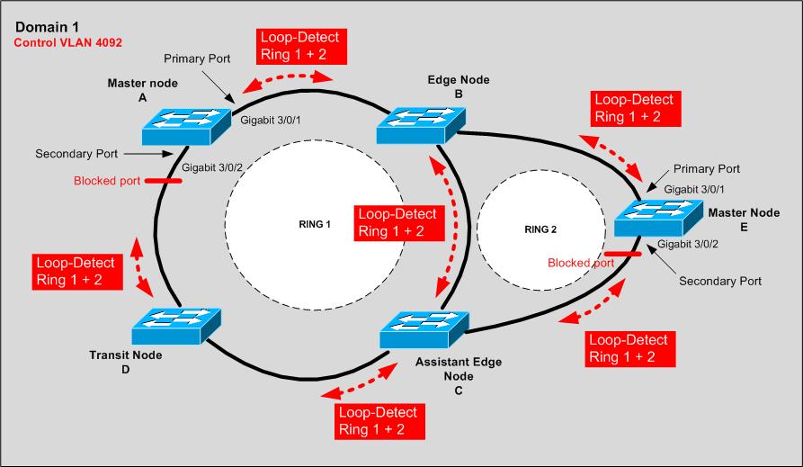
You can note that the control packets really do flood via the whole control VLAN that spans both rings, and they are identified just by the ring ID number.
For this to work, maintain the whole configuration on Device A, B and on C and D and E, you should start with the MSTP and Ring links configurations as in the previous Single Ring configuration example.
For configuring Edge Node B, we create RRPP domain 1, configure VLAN 4092 as the primary control VLAN of RRPP domain 1, and configure the VLANs mapped to MSTIs 0 through 47 as the protected VLANs of RRPP domain 1.
[B] rrpp domain 1
[B-rrpp-domain1] control-vlan 4092
[B-rrpp-domain1] protected-vlan reference-instance 0 to 47
#Configure Device B as a transit node of primary ring 1, with Gigabit 3/0/1 as the primary port and Gigabit 3/0/2 as the secondary port, and enable ring 1.
[B-rrpp-domain1] ring 1 node-mode transit primary-port gigabitethernet 3/0/1 secondary-port gigabitethernet 3/0/2 level 0
[B-rrpp-domain1] ring 1 enable
#Configure Device B as the edge node of sub-ring 2, with GigabitEthernet 3/0/3 as the edge port, and enable ring 2.
[B-rrpp-domain1] ring 2 node-mode edge edge-port gigabitethernet 3/0/3
[B-rrpp-domain1] ring 2 enable
[B-rrpp-domain1] quit
#Enable RRPP.
[B] rrpp enable
For configuring Assistant Edge Node C, create RRPP domain 1, configure VLAN 4092 as the primary control VLAN of RRPP domain 1, and configure the VLANs mapped to MSTIs 0 through 47 as the protected VLANs of RRPP domain 1.
[C] rrpp domain 1
[C-rrpp-domain1] control-vlan 4092
[C-rrpp-domain1] protected-vlan reference-instance 0 to 47
#Configure Device C as a transit node of primary ring 1, with Gigabit 3/0/1 as the primary port and Gigabit 3/0/2 as the secondary port, and enable ring 1.
[C-rrpp-domain1] ring 1 node-mode transit primary-port gigabitethernet 3/0/1 secondary-port gigabitethernet 3/0/2 level 0
[C-rrpp-domain1] ring 1 enable
#Configure Device C as the edge node of subring 2, with GigabitEthernet 3/0/3 as the edge port, and enable ring 2.
[C-rrpp-domain1] ring 2 node-mode assistant-edge edge-port gigabitethernet 3/0/3
[C-rrpp-domain1] ring 2 enable
[C-rrpp-domain1] quit
#Enable RRPP.
[DeviceB] rrpp enable
For configuring Sub-ring Master Node E, create RRPP domain 1, configure VLAN 4092 as the primary control VLAN of RRPP domain 1, and configure VLANs mapped to MSTIs 0 through 47 as the protected VLANs of RRPP domain 1.
[E] rrpp domain 1
[E-rrpp-domain1] control-vlan 4092
[E-rrpp-domain1] protected-vlan reference-instance 0 to 47
#Configure Device E as the master node of subring 2, with GigabitEthernet 3/0/1 as the primary port and GigabitEthernet 3/0/2 as the secondary port, and enable ring 2.
[E-rrpp-domain1] ring 2 node-mode master primary-port gigabitethernet 3/0/1 secondary-port gigabitethernet 3/0/2 level 1
[E-rrpp-domain1] ring 2 enable
[E-rrpp-domain1] quit
#Enable RRPP.
[E] rrpp enable
Some verification commands to try on the real machines.
#Display brief information about RRPP configuration
display rrpp brief
#Display detailed information about RRPP configuration
display rrpp verbose domain domain-id [ ring ring-id ]
#Display RRPP statistics
display rrpp statistics domain domain-id [ ring ring-id ]
#Clear RRPP statistics
reset rrpp statistics domain domain-id [ ring ring-id ]
In summary
Well, in summary I cannot tell if I really like what I see here, innovation is good, but I still do not see a real benefit of Rapid Ring Protection Protocol compared to Rapid Spanning Tree in these topologies. Even in ring topologies, the Rapid STP Proposal/Acknowledgment process would be comparably quick and the configuration much less prone to errors as configuring separate VLANs and have all the rings basically designed only for the loop protection.
But it is good to know there are other things out there to challenge Spanning Tree, like Cisco Flex links, HP Monitor/Smart links, Stacking technologies like VSS and IRF and not one more called Rapid Ring Protection Protocol (RRPP).
I hope you enjoyed something “new” for a change.







Really useful info.Very simple and easy to understand.
great article. thanks for sharing.
This basically sounds like HPs implementation of an EPSR Ring.
See: http://www.alliedtelesis.com/media/fount/how_to_note_alliedware_plus/howto_aw_plus__config_epsr1.pdf
http://en.wikipedia.org/wiki/Ethernet_Automatic_Protection_Switching
Great post but you just miss a little detail!
For recovery the transit node does NOT send messages to the master. The only recovery method is when the master receive the hello message in the secondary port!!
Read:
3. Fault recovery detection and related operations in:
http://www.h3c.com/portal/Products___Solutions/Technology/LAN/Technology_White_Paper/200810/618495_57_0.htm