


HPE’s DCN / Nuage SDN – Part 1 – Introduction and LAB Installation Tutorial
Nuage Networks is a spinoff from Alcatel-Lucent (now under Nokia as they acquisition Alcatel recently) and also a name of software defined network (SDN) overlay solution for datacenters and direct competitor for a bit more widely known vmWare’s NSX. However Alcatel/Nokia are not the only backers here, Hewlett Packard Enterprise (HPE) also got a vested interest in this technology and jumped on the partnership with Alcatel/Nokia generating their own spin-off called “HPE’s Distributed Cloud Networking” or HPE DCN for short. In this article I am going to quickly summarize what it should be capable of doing, and then I am going do a run down of how to install this system in a home lab environment, while trying to minimize the requirements for a home install of this beast sacrificing a few redundancies that you would normally have in a DC setup.
I am marking this article as “Part 1” because this installation will only provide the most very basic overlay solution and there will be follow-ups that will go into different aspects later (e.g. redundancy, cooperation with vmWare ESX high availability or L3 VTEPs). For now we are going to setup a simple lab, trying to minimize the requirements for the HW.
In subsequent Parts 2/3/etc… we are going to be focusing on suing the HPE DCN to create virtual networks, create best redundancy resilience for individual components and get through some interesting use-cases.
Index of article series:
- HPE’s DCN / Nuage SDN – Part 1 – Introduction and LAB Installation Tutorial
- HPE’s DCN / Nuage SDN – Part 2 – First Steps Creating Virtual/Overlay Customer Network
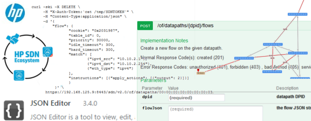
- HPE’s DCN / Nuage SDN – Part 3 – REST API introduction
Contents
Introduction to SDN Overlays
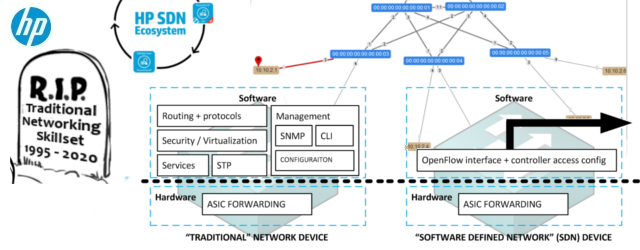
I have already written some SDN articles here on networkgeekstuff.com, but those where more oriented in controlling the real forwarding fabric with SDN, here with Nuage inside DCs, the SDN is actually trying to solve something completely different. Lets start with a problem declaration:
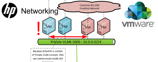
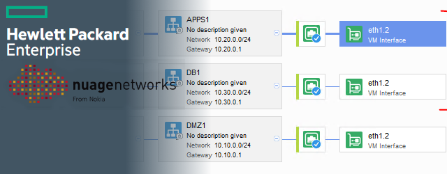
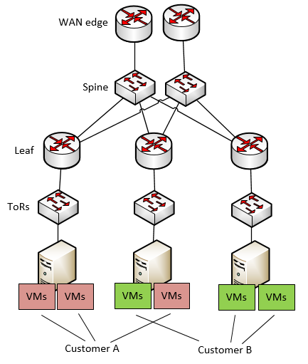
Problem Declaration: I have a DC where I host multiple customers, all having their physical/virtual and other appliances randomly placed inside my underlay (this is a term I am going to use for the internal routing of the DC, not for customers routing). What mechanisms should I choose to separate my customers inside my DC ? Below is a picture of this problem:
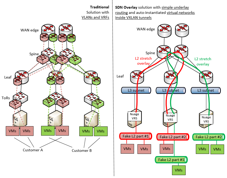
Now if you are a networking guy reading this, your first idea will probably be: “This is easy! This is what we do all the times with VLANs and VRFs!” and you will be partially right. However your are right only as in 1998 people where right that Internet search will be solved by manual indexing before google came and turned everything upside down … we are maybe at that time in networking. In summary, the problem with your solution is that it is manual work configuring every customer box-by-box using VLANs and VRFs.
In contrast, SDN solution like Nuage is trying to solve this problem by deploying a layer of network abstraction/virtualization and keeping the customer networks hidden from the normal traditional network underlay. Because my dear network enthusiast reader, the biggest problem today is simply YOU! Manual work, your salary and the fact that in every project where network is involved, someone has to design a new network always from scratch and manually configure large amount of vendor specific boxes to work as intended … this is why today network is usually the slowest part of any infrastructure project.
So in this tutorial, we are doing to create a quick lab, trying to get the SDN Overlay solution working using the Nuage system.
LAB/HW requirements to follow this tutorial
For this first tutorial (part 1), I will minimize the amount of HW needed and we will not install a few redundant systems to lower the amount of RAM needed. In later follow-up tutorials we will fix this, but for right now we will small.
Knowledge pre-requisites:
This tutorial starts by showing you a vmWare based LAB topology on which you we will be installing the Nuage, we will not show you step by step how to work with vmWare systems here and it is assumed you know this (honestly even if you do not, this is something that you can find elsewhere on the web)
- Ability to install & configure vmWare Workstation 12
- Ability to install & configure vmWare ESXi host hypervisor to a vmWare Workstation virtual host
- Ability to install & configure vmWare vCenter (at least as OVA appliance deployed and you add control over the ESXi hosts to it)
- Basic linux skills (needed to deploy the NFS / DNS and othter basic tools needed)
HW that I have used:
- 64GB or RAM PC with 4core processor supporting VR/AMD-X and nested paging (because we will be using virtualization inside virtualization here)
- NFS server, I have used my home NAS linux simply running NFS-kernel and NFS-common packages
- DNS server that supports also reverse DNS and SRV records declaration, I have used bind9 running at my home
- NTP server or internet access to connect to a public one
SW that I have used:
- vmWare Workstation Pro 12 (you can try VirtualBox but I am 99% sure you will run into problems having ESX hosts inside VirtualBox later)
- ESXi 6.0 (I do not have access to 6.1 yet), evaluation / trial license is enough
- vCenter appliance OVA to control my ESXi virtual hosts, evaluation / trial license is enough
HPE DCN software packages needed:
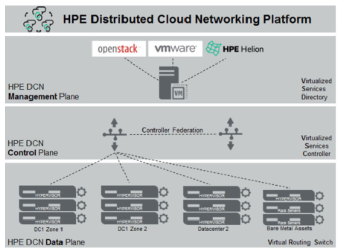
HPE DCN is a platform with three basic components (there are more, but that is for follow-up tutorials) called Virtual Services Directory (VSD), Virtual Services Controller (VSC) and Virtual Routing Switch (VRS), below is a quick picture how they are orchestrating with VSD and VSC forming a control plane and VRS integrated as work horse into every hypervisor or server installed.
In our tutorial, you will need these three packages (I used version 4.03r of HP DCN, Nuage from Alcatel has different versioning):
- VSD as installation ISO (there exists OVA or installation ISO, I will be using the ISO here, but feel free to use OVA to make it more simple for LAB only, in production always use ISO install)
- VSC as OVA package
- VRS as OVA package
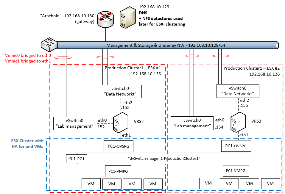
LAB topology
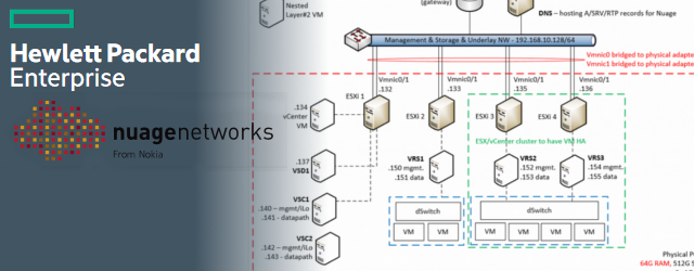
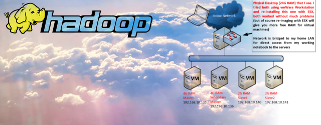
The lab topology is simple in this first toturial to demonstrate the complex overlay over simple underlay. Topology diagram is visible below. The background is simply that I have installed vmWare Workstation 12 on my primary PC (the one with 64G of RAM) and created four virtual machines, each with 16G of RAM and 100G of HDD. On these four virtual machines, I have installed ESXi hypervisors and given them bridged access to my lab network.
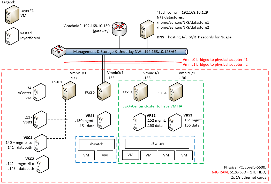
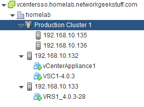
My logic here is that ESX1 – 192.168.10.132 will be my management systems host for vCenter / VSD / VSC and the remaining ESX2 – 192.168.10.133 will be non-redundant ESX host and ESX3 – 192.168.10.135 and ESX4 – 192.168.10.136 will be my redundant ESXi cluster hosts.
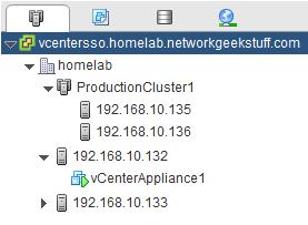
After I have deployed all four ESXi hosts and the vCenter on ESX1, the starting point view on vCenter GUI should be something like this:
LAB DNS, NFS and NTP
Before we jump into installation of Nuage, you need to have the lab setup with DNS, NTP and NFS.
DNS configuration
DNS is needed for nuage to operate as all the main nodes are finding each other using it, this means that you have to have a LAB DNS deployed, in my environment I simply deployed bind9 DNS server on my linux NAS server. Each planned system (both physical and virtual) got a DNS hostname assigned, and I have created a domain “homelab.networkgeekstuff.com”. To save time / space, below are links to my bind9 configuration files, if you have a different DNS system, this is what you need to setup to follow this tutorial:
#HOSTNAME       R.TYPE  IP
vcentersso      A       192.168.10.134

vsd1            A       192.168.10.137
xmpp            A       192.168.10.137
_xmpp-client._tcp.xmpp.homelab.networkgeekstuff.com. SRV 10 0 5222 vsd1.homelab.networkgeekstuff.com.

vsc1man         A       192.168.10.140
vsc1            A       192.168.10.141

vrs1            A       192.168.10.150
vrs2            A       192.168.10.152
vrs3            A       192.168.10.154
You can see above that we need a DNS entry for vcenter, VSD called vsd1 (inclluding allias for XMPP client and SRV record for XMPP), VSC called vsc1 and one extra for its management as vsc1-man and a group of three VRS systems vrs1, vsr2 and vrs3. In bind9 the above I configured inside file db.homelab.networkgeekstuff.com that needs to be placed in /etc/bind directory.
Secondly, your DNS has to support rDNS so that reverse lookups of IP will resolve the hostname of that system, in bind9 this is done by creating db.192 file also inside /etc/bind directory, this file inclues a reverse lookup rules for all the IPs inside local subnet 192.168.10.128/64 that I am using.
The last configuration file is named.conf.local which already exists in your bind install, but you have to update it to point to the two new files I mentioned above.
Hint: If you are configuring bind9 for the first time, do not forget to also edit /etc/bind/named.conf.options and add to “forwarders {};” your normal ISP DNS servers where bind should forward your DNS queries if it doesn’t have them locally inside your local database.
NTP configuration
I simply used internet NTP server randomly from the linux NTP client package, simply take one that you are maybe already using or if your not using anything, write down for the moment this IP 193.171.23.163 that I have used, we will need to use this durin VSD and VSC installation.
NFS configuration
In this tutorial, I am going to show how nuage is installed for a stand alone ESXi host and also a cluster of ESXi hosts for creating a baseline for having a real high availability (HA) for our simulated customers VMs. For vCenter to create a cluster of ESXi you need a shared storage for this cluster to use which is outside of the cluster, for this reason I have used a simple NFS storage that you can get from any linux host (including a VM running inside some other ESX or your vmWare Workstation in worst case) with the following example commands:
#1 - install

apt-get install nfs-kernel-server nfs-common

#2 - create exports

mkdir /home/<your user>/NFS
mkdir /home/<your user>/NFS/datastore1
mkdir /home/<your user>/NFS/datastore2
chown -R nobody:nogroup /home/<your user>/NFS
chmod -R 755 /home/<your user>/NFS

#3 edit /etc/exports and ad there these two lines:

/home/<your user>/NFS/datastore1   *(rw,insecure,all_squash,no_subtree_check)
/home/<your user>/NFS/datastore2   *(rw,insecure,all_squash,no_subtree_check)

#4 restart the nfs-kernel-server

service rpcbind start
service nfs-common restart
service nfs-kernel-server restart
exportfs -ra
Step 1. Installing VSD (stand-alone)
For VSD that I will from this point call it VSD1 because of it’s DNS hostname, in this tutorial we will go for a stand-alone installation type (part 2 of this tutorial in the future will show how to deploy this in 3+1 HA cluster mode). As VSD1 server, I have deployed a 16G RAM virtual machine (note that by requirements the VSD in production should have a minimum of 24G of RAM, but 16G is more than enough for lab use) in my management ESX1 host.
a) Install CentOS 6.7 as base OS for VSD1
My Nuage version 4.03r said that CentOS 6.5+ is supported, but please note that CentOS 6.8 is actually not yet compatible with the VSD installation, so you have to use CentOS 6.7 to have a success here (and I learned this the hard way).
b) Make sure NTP is synchronized
VSD installation and running requires that the base OS clock is synchronized with NTP, if you do not have it running or installed, install NTP package using “yum install ntp” and run it using “service ntp start” to get it synchronized. Then check with “ntpstat” if it is synchronized, success looks like this
[root@vsd1 ~]# ntpstat
synchronised to NTP server (193.171.23.163) at stratum 2
   time correct to within 33 ms
   polling server every 256 s
c) Run installation from ISO on VSD1
Grab the VSD ISO installation package ( in my case DCN-VSD-ISO-4.0R3.zip), unpack it and either connect it as CDROM to the VM or simply upload all the contents of the ISO as files to the VSD1 VM. Since I mounted the iso as virtual CDROM to the VM, i accessed the ISO as follows:
[root@vsd1 ~]# mount /dev/scd0 /media/CDROM/
mount: block device /dev/sr0 is write-protected, mounting read-only
[root@vsd1 ~]# cd /media/CDROM/
[root@vsd1 CDROM]#
And from this you can start the installation script with “./install.sh” and answer all the questions of the wizard driving towards a stand alone installation as on the example below:
[root@vsd1 CDROM]# ./install.sh
-------------------------------------------------------------
  V I R T U A L I Z E D  S E R V I C E S  D I R E C T O R Y
  version 4.0.3_26
-------------------------------------------------------------
VSD supports two configurations:
1)  HA, consisting of 3 redundant installs of VSD.
2)  Standalone, where all services are installed on a single machine.
Is this a redundant (r) or standalone (s) installation [r|s]? (default=s): s
Deploy VSD on single host vsd1.homelab.networkgeekstuff.com  ...
VSD node:      vsd1.homelab.networkgeekstuff.com
Continue [y|n]? (default=y): y
Starting VSD deployment. This may take as long as 20 minutes in some situations ...
VSD package deployment and configuration DONE. Please initialize VSD.
DONE: VSD deployed.
Starting VSD initialization. This may take as long as 20 minutes in some situations ...
<omitted>
After a few more lines you should see a success message that the VSD is installed successfully and it will also by default start running.
d) Verify that VSD is running and stop/start
The VSD start/stop and status is controlled by a monitoring daemon behind a “monit” command. The three main commands to check status are:
[root@vsd1 ~]# monit summary
The Monit daemon 5.17.1 uptime: 4h 12m

Process 'zookeeper'                 Running
Program 'zookeeper-status'          Status ok
Program 'vsd-core-status'           Status ok
Program 'vsd-common-status'         Status ok
Program 'ntp-status'                Status ok
Process 'mysql'                     Running
Program 'mysql-status'              Status ok
Process 'mediator'                  Running
Program 'mediator-status'           Status ok
File 'jboss-console-log'            Accessible
File 'monit-log'                    Accessible
File 'mediator-out'                 Accessible
File 'zookeeper-out'                Accessible
Program 'keyserver-status'          Status ok
Process 'jboss'                     Running
Program 'jboss-status'              Status ok
Program 'ejbca-status'              Status ok
Process 'ejabberd'                  Running
Program 'ejabberd-status'           Status ok
System 'vsd1.homelab.networkgeekstuff.com' Running
[root@vsd1 ~]# monit -g vsd-core summary
The Monit daemon 5.17.1 uptime: 4h 12m

Program 'vsd-core-status'           Status ok
Process 'mediator'                  Running
Program 'mediator-status'           Status ok
Program 'keyserver-status'          Status ok
Process 'jboss'                     Running
Program 'jboss-status'              Status ok
Program 'ejbca-status'              Status ok
[root@vsd1 ~]# monit -g vsd-common summary
The Monit daemon 5.17.1 uptime: 4h 12m

Process 'zookeeper'                 Running
Program 'zookeeper-status'          Status ok
Program 'vsd-common-status'         Status ok
Process 'mysql'                     Running
Program 'mysql-status'              Status ok
Process 'ejabberd'                  Running
Program 'ejabberd-status'           Status ok
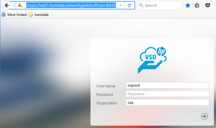
Additionally, you should now be able to login to VSD using web interface (default login csproot/csproot and organization “csp”) in port 8443, for my case this was https://vsd1.homelab.networkgeekstuff.com:8443
If you ever need to shutdown the VSD, you can use:
monit -g vsd-core stop
monit -g vsd-common stop
and monitor the status until everything is stopped, similarly, to start the vsd again you can use
monit -g vsd-common start
# wait until all in common is tarted before starting core part!
monit -g vsd-core start
Great, if you are here, you have your VSD1 installed successfully and we can proceed to installing VSC now.
Step 2. Installing VSC (stand-alone)
VSC installation itself is very simple because for vmWare it is integrated in template customization when deploying OVF template, the interesting part comes when configuring it because VSC is technically an Alcatel Lucent router system with a very specific command prompt. But without more delay, here is the process:
a) Deploy OVF template of VSC to ESX1 host
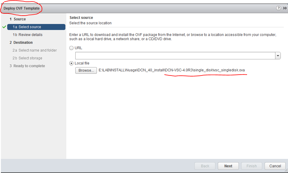
Follow the typical OVF deployment process, Just note that ths VSC has two network interfaces, one is managment and one is data (production) network, since we are only using one network here, give the VM access to the lab network on both interfaces. If you look back above to my lab topology, you will notice that I have provided IP addresses to both interfaces from the same subnet. In production environment, these two interfaces should go to different networks, one for managment and one for data traffic underlay.
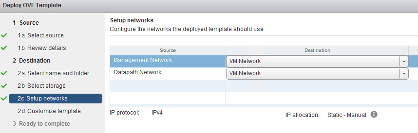
On one point the OVF deployment process comes to VM template customization and will ask you several parameters to be filled manually. We have to give the VSC its IPs on both intefaces, DNS server IPs, default gateway and most of the parameters are self-explanatory and below is my configuration for my lab:
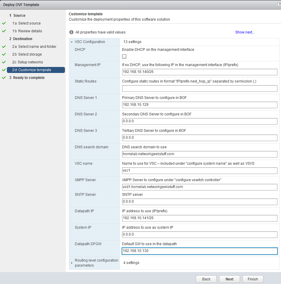
Hint: In the above configuration, the XMPP server should be pointing to vsd1, not to the xmpp DNS record that we have cerated for stand-alone VSD installations, if you configure this to the XMPP (thinking that the DNS is pointing to the same IP! you are going to get a XMPP negotiation problems because the VSC is going to contact “xmpp”, while response ID will be from vsd1 as source inside the XMPP protocol). We will be re-configuring this only later in cluster VSD deployments.
b) login into the VSC and configure XMPP
Now after the VSC is deloyed, you can start it and after a while you will be able to login to it using SSH and default credentials “admin/Alcateldc”. The next thing that we need working is XMPP connection to vsd1, this can be checked with “show vswitch-controller vsd” command and by default, there will be nothing and we have to fix a small parameter syntax to make it working as shown below the whole process:
*A:vsc1# show vswitch-controller vsd

===============================================================================
Virtual Services Directory Table
===============================================================================
User Name                       Uptime             Status
-------------------------------------------------------------------------------
No Matching Entries
===============================================================================

*A:vsc1# config vswitch-controller
*A:vsc1>config>vswitch-controller# info
----------------------------------------------
        xmpp-server "vsc1@vsd1.homelab.networkgeekstuff.com"
        open-flow
        exit
        xmpp
        exit
        ovsdb
        exit
----------------------------------------------

* indicates that the corresponding row element may have been truncated.
*A:vsc1>config>vswitch-controller# shutdown
*A:vsc1>config>vswitch-controller# xmpp-server "NSC-vPE1:password@vsd1.homelab.networkgeekstuff.com"
*A:vsc1>config>vswitch-controller# no shutdown
*A:vsc1>config>vswitch-controller# show vswitch-controller vsd

===============================================================================
Virtual Services Directory Table
===============================================================================
User Name                       Uptime             Status
-------------------------------------------------------------------------------
cna@vsd1.homelab.networkgeekst* 0d 00:02:38        available
-------------------------------------------------------------------------------
No. of VSD's: 1
===============================================================================
* indicates that the corresponding row element may have been truncate
The problem that we fixed above was that the OVF deployment template didn’t followed a correct syntax and we needed to add a default password “password” to the configuration and I have optionally changed the name to NSC-vPE1. Afterwards the show vswitch-controller vsd command showed an active connection to the VSD.
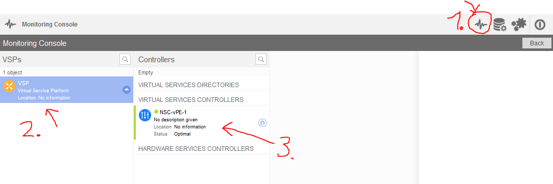
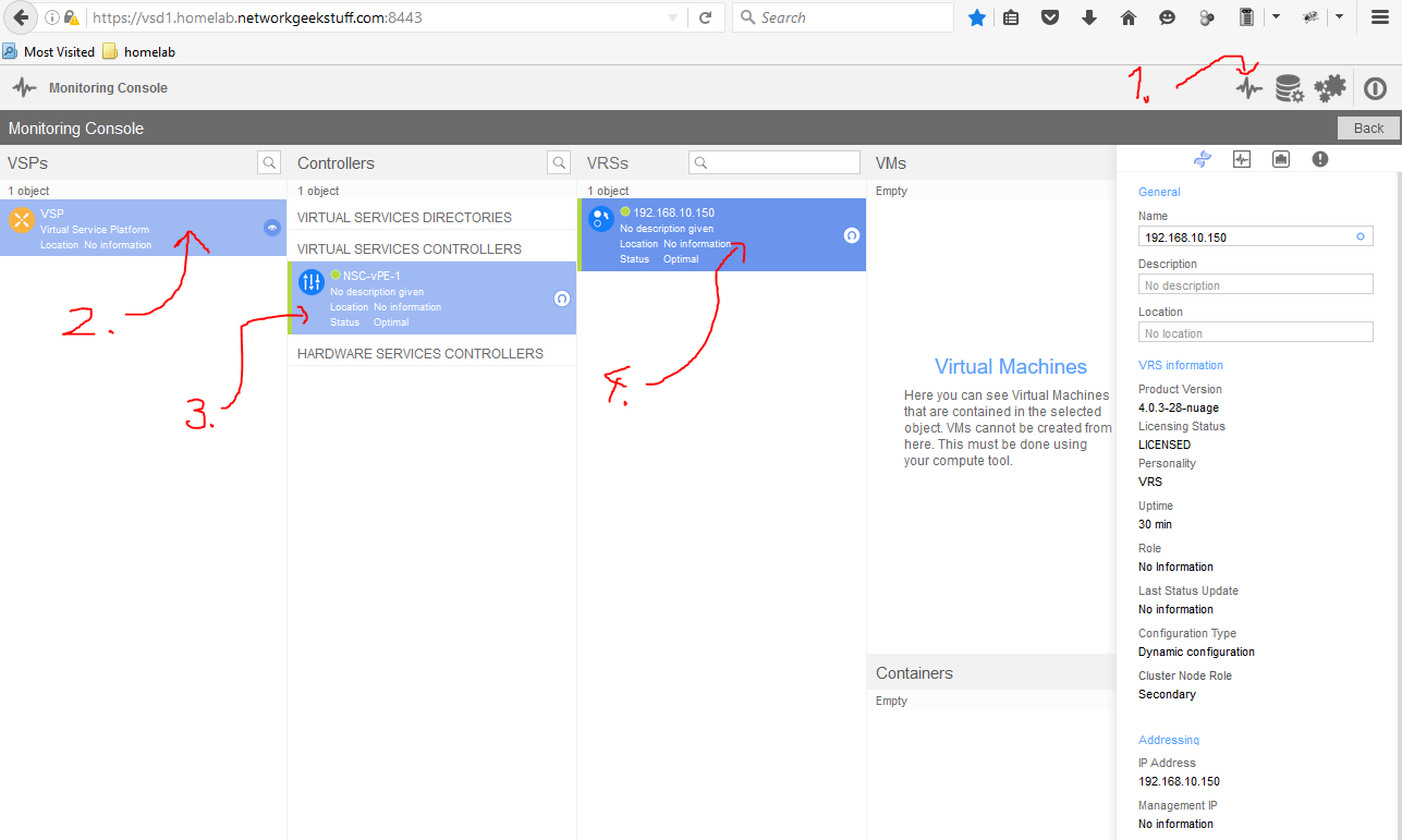
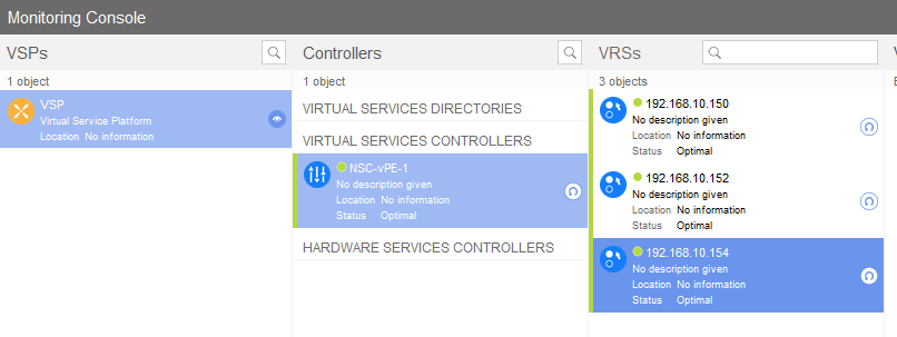
c) Verify VSC visible from VSD
This check is actually simple, login to the VSD web gui (check above VSD installation steps to know how) and open the monitoring tab, then click VSP and you should see your VSC box registered there (green color means alive, red -> unreachable).
Step 3. Installing VRS to standalone ESXi host
In this step, we are going to install the last component called VRS (virtual router-switch) to a stand alone ESXi host. If you have an ESXi cluster, the process is very similar and I recommend you read the guide for a single ESXi host first, and then I created below optional “Step 4” for ESXi hosts that only shows the differences (for time / space reasons), but has some specialties that I wanted to mention separately.
Principle of VRS orchestration
The VRS is practically a virtual machine (VM) running on the ESXi host similarly like all other VMs, the difference is that it is trying to be also a network appliance and as such demands to be orchestrated inside the ESXi host using a specific setup of VMwares internal vSwitches and distributed vSwitches. To ilustrate this, have a look at the configuration that I will be creating in this part of the tutorial:
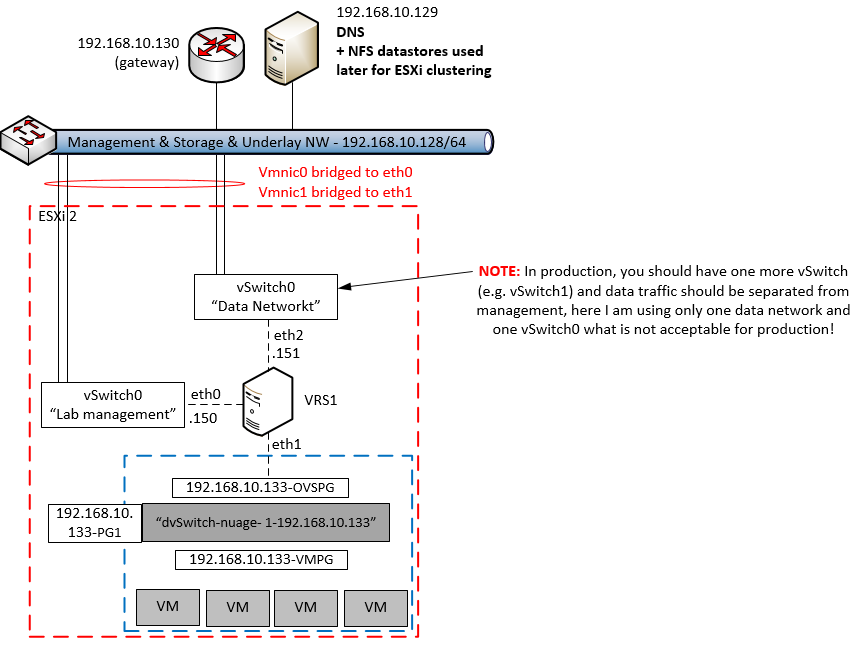
On the diagram above, you can see that a single ESXi host (red border) in my lab will use a sequence of both VMware’s dSwitch (called “dvSwitch-nuage-1-192.168.10.133”), Nuage VRS (called “VRS1”) and older VMware’s “vSphere vSwitch” (called “vSwitch0”). The purpose of individual components is as follows:
- VMware dSwitch – “dvSwitch-nuage-1-192.168.10.133”: This is the switch used to aggregate traffic from all the end user virtual machines (VMs) and push it to VRS for processing. It has two main port groups, one is called VMPG that is for communication with the virtual machines and one called OVSPG that is a promiscuous port configured to allow all traffic of the VMs to be visible to the VRS.
- VRS1 – The VRS itself running as just another VM on the ESXi host (we will be deploying this simple with OVF template deployment later), the purpose of this box is to capture all other VM traffic and process it as instructed by the VSD/VSC. It should communicate with VSD/VSC via “Management interface” and with other VRSs and VRS-Gs via “data network”. Note that in our lab for simplicity we have management and data network merged behind one and the same “vSwitch0” which should definitely NOT be the case if you are building a production.
- vSwitch0 (as access to “Lab management” and “Data Network”), in our LAB deployment, we will be simply connecting the management and data network interface of VRS to the same vSwitch0, this will give our VRS access to the lab simple network and it will work correctly, however for any production deployment it is very much recommended to create one extra distributed vSwitch or vSphere vSwitch (ergo here it would be vSwitch1) that would separate managment network (communication with VSC/VSDs) and data network (forwarding traffic between all the VRSs and VRS-Gs).
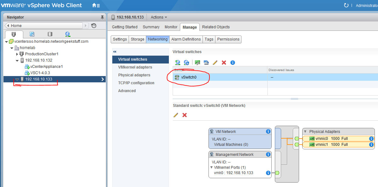
1. Preparing the ESXi host networking
We are starting here with a freshly installed ESXi host, that by default has one standard “vswitch0” and both management and physical interfaces connected to it as visible in the picture below taken from vCenter’s view on this ESXi host:
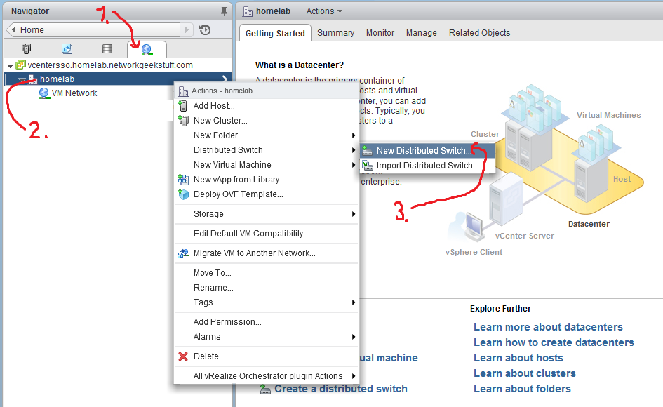
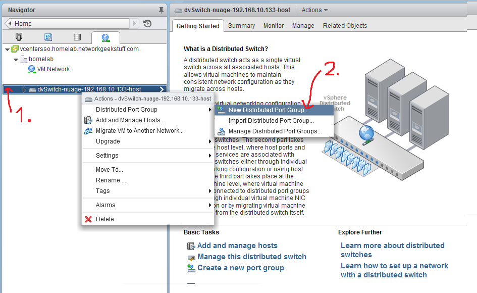
1.1 Deploy VMware distributed switch
What we need to do is to deploy a VMware distributed switch with a special configuration before installing VRS. We can deploy this by clicking Networking -> homelab (or name of your DC) -> Distributed Switch -> “New Dsitributed Switch…” like on the picture below:
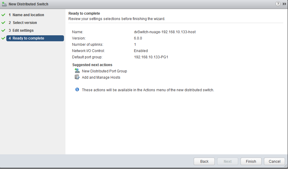
Configuration of the new dSwitch:
- Name: In the wizard, I am going to name this switch as “dvswitch-nuage-192.168.10.133-host” because this distributed switch will be exclusively deployed to this single ESXi host later.
- Version: Simply latest, I am using 6.0.
- Uplinks: We do not need any uplinks for this switch because it is going to be used between customer VMs and VRS only, but VMware wants us to declare a minimum of 1 uplink, so lower the uplinks number to minimum which is 1
- Default port group: Create one default port group that is ending with “-PG1” in name, for example I have created “192.168.10.133-PG1”.
Here is a summary picture from my deployment:
1.2. Add extra port groups to dSwitch
In addition to the default “-PG1” port group, our dSwitch needs two more port groups with special configurations. So via the Networking menu, open “New Distributed Port Group..” wizard as shown below:
Create the following port-groups with the following configuration:
- <your-ESXi-host>-OVSPG
VRS will be looking for one port group with name ending as “-OVSPG” so for example I have created for myself a port group called “192.168.10.133-OVSPG”.Configuration- Advanced: Make “Block ports” / “Vendor configuration” / “VLAN” allowed
- Security: Change to “Accept” all three items -> “Promiscuous mode” / “MAC address changes” / “Forged transmits”
- VLAN: Change to VLAN type – “VLAN trunking” and trunk range “0-4094”
- Uplinks: Do not add any uplinks (Default)
- <your-ESXi-host>-VMPG
VRS will be looking for one port group with name ending as “-VMPG” so for example I have created for myself a port group called “192.168.10.133-VMPG”.Configuration- Advanced: Leave defaults
- Security: Leave defaults (ergo in 6.0 all items are “Reject” state)
- VLAN: Change to VLAN type – “VLAN” and select a VLAN number of your choice, if you have no specific VLAN logic, simply select “2”
- Uplinks: Do not add any uplinks (Default)
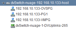
After your configuration of all port-groups, the final view on this dSwitch should be similar to this:
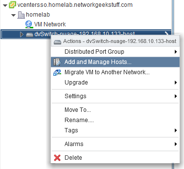
1.3 deploy dvSwitch to ESXi host
Yes, the dSwitch you created is not yet deployed on the specific ESXi host we are targeting, therefore simply add your host to the dSwitch via “Add and Manage Hosts..” wizard found in Networking area of vCenter. Note: Simply deploy the dvSwitch and do not migrate to it anything! Do not move VMkednel or physical adapters like the wizard would like to do by default.
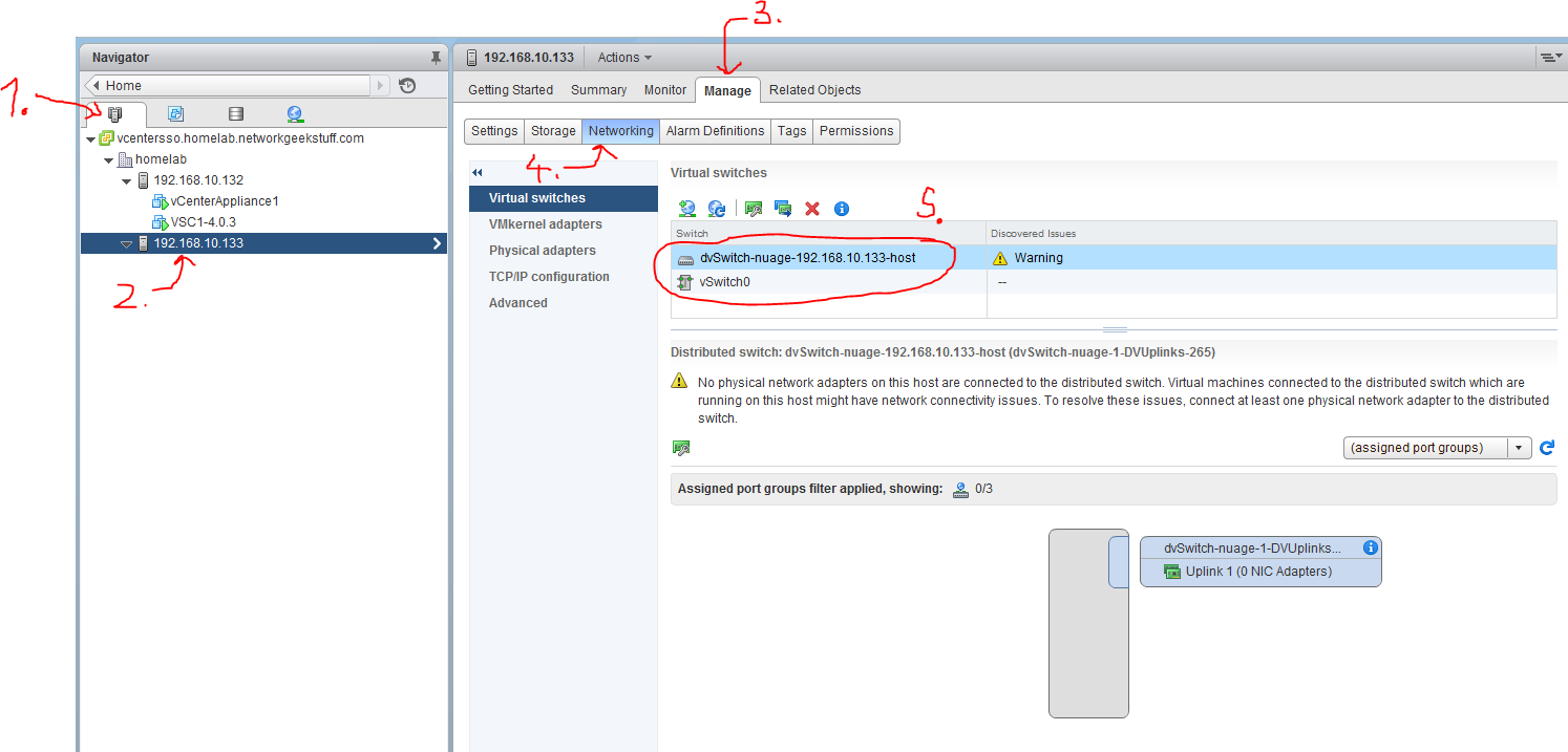
To check if your deployment was successfull, you have to go back to Hosts view and check the Manage->Networking view if both vSwitch0 and the new distributed vSwitch are present on the host like below:
2. Deploying VRS image to the ESXi host
Now finally we will get to the VRS deployment itself. Fortunatelly for you, this is actually a very quick step as VRS on vmWare is using a customized OVF deployment with all the configration parameters of VRS you can enter using vCenter GUI before the VRS VM is started for the first time.
You start by simply opening “Deploy OVF Template..” wizare in your vCenter (righ click on the ESXi Host) and navigate to the VRS.ovf files that you should have access to.
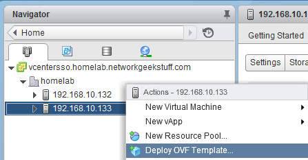
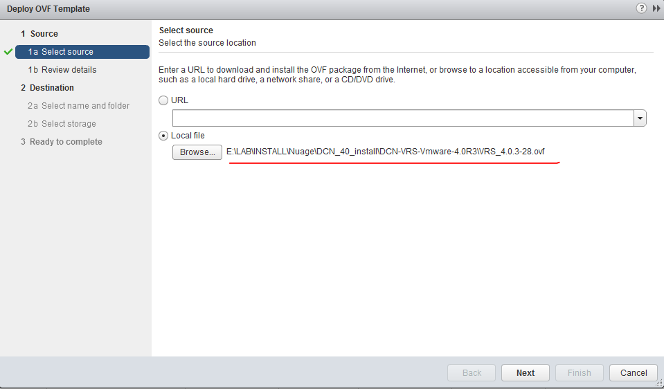
Hit “next” and the vCenter will start loading the OVF file. I am going to skipp the vCenter VM configuration here because you should simply continue as with any other VM, that is select a storage datastore in the local ESXi cluster, this VM is bound to the ESXi host so you should not think about this VM redundancy as outside of this ESXi host it is useless anyway.
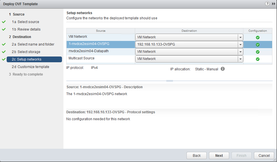
The first important configuration is “Setup Networks” where we have to stop and select correct interface connection. Configure your VRS VM network interfaces as follows:
- “VM Network” – This is this VMs management interface, in our lab as shown above, we will simply use our “vSwitch0” connection with by default has a port-group called “VM Network” (note: This is a bit confusing as the VRS interface and the default vSwitch0 portgroup has the same name, but usually this can be any portgroup / vSwitch or dSwitch that leads to managment network, the name “VM Network” is not demanding connection to this default port range).
- “1-mvdce2esim04-OVSPG” – This is the VRS communication channel (the promisous one if you remember the port-group configuration) to all the distributed dvSwitch, configure this to connect to the “<your-host>-OVSPG” interface, in my case the “192.168.10.133-OVSPG”.
- “mvdce2esim04-Datapath” – this is connection/interface to the “Data network”, which if you remember in my lab is the same as management network, so in my lab I am also going to confige this tot he default vSwitch0 portgroup called “VM Network” that will lead to my LAB central subnet.
- “Multicast Source” – this is the interface via which VRS can provide support for Multicast traffic in the Overlay / Virtual SDN networks, but this is out of scope of this tutorial and also basic use cases. The only note that I leave you with is that this can be yet another vSwitch or dvSwitch that can lead to a dedicated interface used for multicast traffic.
Here is how I have configured my VRS at the end with interfaces, since my LAB merged data network , managemnt network and possibly in the future multicast network behind the default vSwitch0, it looks quite boring.
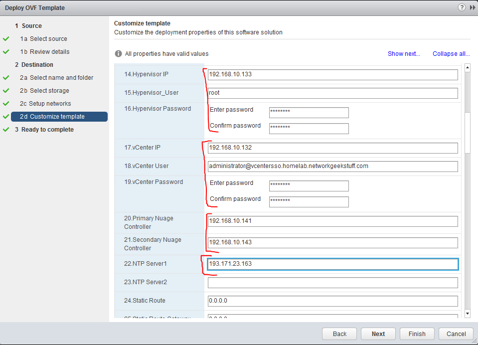
The second important configuration page in the OVF deployment is called “Customize template”, there are roughly 13 fields that are mandatory to be filled, most of them are self-explanatory and there is detailed explanation in the Nuage installation guide, for making this quick for our LAB, I am going to show you how I configured my VRS and the most important thing are :
- Management IP / netmask /gateway / DNS
- Data IP /netmask /gateway / DNS
- Hypervisor IP + username/password (this is important as VRS agent needs to read hypervisor API information)
- vCenter IP + username/password (as above, VRS agent needs to read vCenter API information)
- Controller (VSC) IPs, it wants primary and backup controller, we unfortunatelly have only one, so I used our VSC1 controller IP : 192.168.10.141 and then as backup used a non-existing 192.168.10.143. In next parts of this guide we will use this when we will be deploying VSC redundancy.
- NTP: Used the internet IP 193.171.23.163
Here are screenshots how it looks in the OVF deployment:
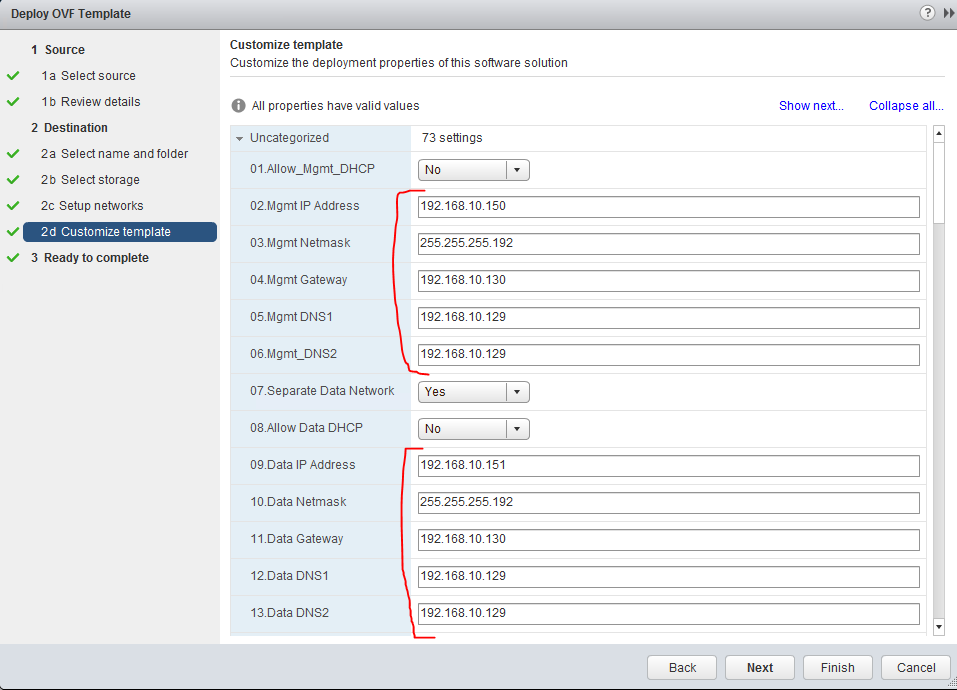
Once deployment is done, simply start the VM.
3. checking VRS install
Now we have VSD, VSC and VRS all running, it is time to check if they all see each other.
First, let look via VSC because this one has a session with both VSD and VRS (you should remember that for VSC you can access it via SSH with admin/admin credentials). Once inside VSC, us the show vswitch-controller vswitches command to show all VRSs that registered to this VSC successfully.
*A:NSC-vPE-1# show vswitch-controller vswitches

===============================================================================
VSwitch Table
===============================================================================
vswitch-instance               Personality Uptime       Num VM/Host/Bridge/Cont
-------------------------------------------------------------------------------
va-192.168.10.150/1            VRS         0d 00:24:16  0/0/0/0
-------------------------------------------------------------------------------
No. of virtual switches: 1
===============================================================================
The second option is more simple, you can simply view all components via VSDs monitoring tab.
Step 3.b (optional) Installing VRS on ESXi cluster
Lets start by principle explanation, VMware clusters exist to provide redundancy and distributed resource allocations to VMs, in my lab, I have installed a small cluster using two ESXi hosts, one is 192.168.10.135 and second 192.168.10.136 and I have added them to a cluster called “Production Cluster 1” as visible on picture below from vCenter:
Now in regards to VRS deployment, the principle is that each ESXi host inside a cluster should get its own VRS. This helps give the cluster an overall performance as having single VRS per cluster is also possible (think about the dvSwitch configuration), but there is no real reason to do it like that. Each VRS should be deployed as a VM to each specific ESXi host with VMware’s HA (high availability) disabled for that VM because there is no point of moving VRS to another ESXi host on failure as that would create two VRS VMs on single ESXi and would lead to collision.
Below is a high level view on how to install two VRSs on a cluster of two ESXi hosts that I deployed in my lab.
The important part to take from the above picture is that the dvSwitch component and vSwitch0 components are deployed identically as with a single ESXi host and as such there is no difference in the installation process, you should simply again define a dvSwitch with -OVSPG and -VMPG port groups like shown in this tutorial for a single ESXi host, but then deploy this dvSwitch on both members of this cluster and install two VRSs to each member following the OVF template deployment.
Afterwards, your vCenter view should look like this:
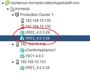
While in your VSC console, you should be able to display all three VRSs now (two on cluster and one from the previous install on single ESXi):
*A:NSC-vPE-1# show vswitch-controller vswitches

===============================================================================
VSwitch Table
===============================================================================
vswitch-instance               Personality Uptime       Num VM/Host/Bridge/Cont
-------------------------------------------------------------------------------
va-192.168.10.150/1            VRS         0d 02:03:25  0/0/0/0
va-192.168.10.152/1            VRS         0d 00:28:41  0/0/0/0
va-192.168.10.154/1            VRS         0d 00:23:40  0/0/0/0
-------------------------------------------------------------------------------
No. of virtual switches: 3
===============================================================================
And also in your VSD it should see all three VRSs registered
Summary
This guide showed you how to install basic HP DCN / Nuage system and you should now play on your own in the VSD gui to create some virtual networks yourself.
References
- Nuage/ALU homepage
- HPE DCN homepage
- HPE DCN White Papers / DataSheets / Solution Guides
- HPE DCN Documentation / Manuals (Install guide and User guide is here!)
If you do not want to decode user guide on what to do next here, youu can wait for the “upcomming” part 2 of this tutorial we will go over basic steps how to design and create a virtual network for our customer and deploy some customer VMs that the VRS/VSC will auto-detect. And in pert 3 later, we will be upgrading all components to make them redundant, ergo making a VSC cluster and also installing the VSD as a cluster of three boxes. Stay tuned!
Index of article series:
Was Very Informative Peter,
Thank you
Great – thanks from Nuage!
Hi Peter
is all the software for lab purposes freely available?
thanks
Thomas
Not really, I have to admit that I got access to this software because of where I work via internal channels, you would have to contact nuagenetworks.net pre-sales for a demo license.
Peter
Great job!!!! Keep up the Good Work.
Could not Thank you enough.
Thank you.
Great document.
Any details/steps on redundant VSCs?
Thanks.
Not in this articles as this tries to create a minimal system for people that have limited lab.
However creating a redundant VSC is the same process as with the primary VSC, the only extra step needed is to enter the two VSCs consoles and create a BGP session between them with config like this (change AS number and IPs as needed)
autonomous-system 65000
#————————————————–
# echo “BGP Configuration”
#————————————————–
bgp
connect-retry 2
min-route-advertisement 1
outbound-route-filtering
extended-community
send-orf
exit
exit
router-id 29.203.0.10
rapid-withdrawal
rapid-update evpn
group “internal”
type internal
neighbor 29.203.0.11
family evpn
exit
exit
no shutdown
exit